
Manual

2 Installation
761 SD Compact IC / Instructions for Use 8.761.1043
20
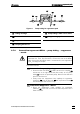
2.6.7 Connection suppressor → waste
Route the "suppressor outlet capillary for eluent ("Waste")" 44 at the rear
out of the 761 SD Compact IC into a waste container.
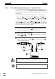
2.7 Installing the regenerant path
The regenerant (100 mmol/L H
2
SO
4
) is aspirated with the peristaltic
pump from the regenerant MPak and forced into the suppressor via the
filter unit PEEK. From the suppressor, it is then routed into a waste con-
tainer (see Figure 9).
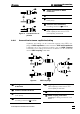
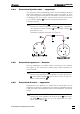
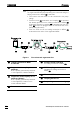
2.7.1 Fitting the pump tubing for regenerant
One channel of the two-channel peristaltic pump is used to pump the
regenerant. Fit a pump tubing 61 6.1826.110 as follows:
1 Disengage the tubing cartridges
• Detach and disengage the two tubing cartridges 57 above
the pump drive 49 by pressing in the snap-action lever 59 on
the retaining bracket.
• Press the pressure lever 58 down fully.
2 Fit the couplings 60
• Fit one coupling 60 6.2744.110 onto each end of the pump
tubing 61 6.1826.110. Moistening the tip of the coupling
lightly will make it easier to slip it on.
3 Fit the pump tubing
• Insert the fitted pump tubing 61 as shown in Figure 8 into the
tubing cartridge. The left-hand stopper 62 should latch into
the corresponding fixture on the left-hand side of the tubing
cartridge.
4 Reengage the tubing cartridge
• Reengage the tubing cartridge with pump tubing 61 in the re-
taining bracket. Engage it at the left first and then press the
right-hand side down until the snap-action lever 59 engages.
Ensure that the pump tubing is not kinked when doing this.
• Leave the other tubing cartridge outside. It is fitted with the
pump tubing for the sample path (see Section 2.8.1).