761 SD Compact IC CH-9101 Herisau/Schweiz E-Mail info@metrohm.com Internet www.metrohm.com 8.761.
CH-9101 Herisau/Schweiz E-Mail info@metrohm.com Internet www.metrohm.com 761 SD Compact IC 761 SD Compact IC POWER 8.761.1043 Instructions for Use 8.761.1043 02.
Teachware Metrohm AG Oberdorfstrasse 68 CH-9101 Herisau teachware@metrohm.com 1. Edition 2004 These instructions are protected by copyright. All rights reserved. Although all the information given in these instructions has been checked with great care, errors cannot be entirely excluded. Should you notice any mistakes please inform the author at the address given above.
Table of contents Table of contents 1 Introduction ................................................................ 1 1.1 1.2 Instrument description ................................................................................1 Parts and controls .......................................................................................3 1.2.1 1.2.2 1.2.3 Front view ........................................................................................................... 3 Rear view .....................
Table of contents 2.12 Connection to the PC ................................................................................30 2.12.1 2.12.2 2.12.3 2.12.4 Connecting cable 6.2134.100.......................................................................... 30 Software installation ......................................................................................... 30 Basic settings «IC Net».....................................................................................
Table of contents 6.2 Maintenance and servicing .......................................................................91 6.2.1 6.2.2 6.2.3 6.2.4 6.2.5 6.2.6 6.2.7 6.2.8 6.2.9 6.3 6.4 General information .......................................................................................... 91 Passivation........................................................................................................ 91 Shutdown....................................................................................
Table of contents List of figures Figure 1: Front of the 761 SD Compact IC ............................................................... 3 Figure 2: Rear panel 761 SD Compact IC ................................................................ 4 Figure 3: Connection schematic for 761 SD Compact IC ........................................ 5 Figure 4: Connectors for capillaries........................................................................ 13 Figure 5: PEEK couplings................................
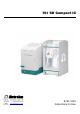
1.1 Instrument description 1 Introduction 1.1 Instrument description The 761 SD Compact IC is a version of the time-proven 761 Compact IC which has been developed specifically for soft drink analysis. The 761 SD Compact IC is designed for determining phosphoric acid and its intermediate products in soft drinks but also continues to offer all functionalities of the original version.
1 Introduction All components coming into contact with eluent and sample are metalfree. Ready-to-use eluents in certified MPaks are supplied for soft drink analysis. The 761 SD Compact IC is operated by means of a PC connected to the RS232 interface. The 761 SD Compact IC can be controlled by the «IC Net» software or by the “master” «IC Cap» software. The systems required for soft drink analysis (and the methods linked to them) are supplied on the installation CD.
1.2 Parts and controls 1.2 Parts and controls In this section you will find the numbers and designations of the parts and controls of the 761 SD Compact IC. The numbering applies throughout the instructions for use, i.e. bold numbers in the text (e.g. 4) refer to the parts and controls illustrated here. 1.2.
1 Introduction 1.2.2 Rear view 8 9 10 Waste B Waste A 11 11 12 Transport security screws 17 Type 1.761.
1.2 Parts and controls 1.2.3 Connection schematic 25 24 34 32 31 55 28 26 33 36 35 37 43 56 38 54 39 40 56 41 42 45 27 48 29 47 44 30 63 64 3 23 50 65 50 61 55 48 46 56 49 23 22 Figure 3: 3 Connection schematic for 761 SD Compact IC Aspirating tubing for sample 22 MPak cabinet for suspending eluent and regenerant bag 23 Tubing connection to MPak 6.1837.000 24 Pump head 6.2824.
1 Introduction 32 Sample loop 1.5 µL (6.1825.240) PEEK sample loop 33 Column connection capillary PEEK capillary 6.1831.010, length L = 30 cm 34 Metrosep RP Guard 6.1011.020 Precolumn for protecting the separating column 35 Connection capillary PEEK connection capillary between precolumn and separating column 36 Metrosep A Supp 1 HS separating column (6.1005.
1.3 Information on the Instructions for Use 1.3 Information on the Instructions for Use Please read through these Instructions for Use carefully before you put the 761 SD IC Compact IC into operation. The Instructions for Use contain information and warnings to which the user must pay attention in order to assure safe operation of the instrument. 1.3.1 Organisation These Instructions for Use 8.761.
1 Introduction 1.3.2 Notation and pictograms The following notations and pictograms (symbols) are used in these Instructions for Use: Fill SYSTEM STATE Menu item, parameter or entry value in the software Program window in the software Button in the software 20 Part or control of 761 SD 18 Part or control of 766 Hazard This symbol draws attention to a possible danger to life or of injury if the associated directions are not followed correctly. .
1.4 Safety notes 1.4 Safety notes 1.4.1 Electrical safety While electrical safety in the handling of the 761 SD Compact IC is assured in the context of the specifications IEC/EN 61010-1 (prot. class 1, degree of protection IP20), the following points should be noted: • Mains connection Setting of the mains voltage, checking the mains fuse and the mains connection must be effected in accordance with the instructions in section 2.11.
2 Installation 2 Installation 2.1 Flow chart The following flow chart provides an overview of all installation work. You will find more detailed information in the relevant section. Setting up sect. 2.2 Installing detektor block sect. 2.4 Installing drain tubes sect. 2.5 Installing eluent flow path sect. 2.6 Installing regenerant flow path sect. 2.7 Installing sample flow path 766 IC Sample Processor sect. 2.8 Yes Connection to 766 IC Sample Processor sect. 2.9 No Replace rear panel sect.
2.2 Setting up the instrument 2.2 Setting up the instrument 2.2.1 Packaging The 761 SD Compact IC is supplied together with the separately packed accessories in special packagings containing shock-absorbing foam linings designed to provide excellent protection. The instrument itself is packed in an evacuated polyethylene bag to prevent the ingress of dust. Please store all these special packagings as only they assure transport of the instrument free from damage. 2.2.
2 Installation 2.3 Description of the connections 2.3.1 Connection of capillaries/tubing The connections for eluent, sample and regenerant consist of: • PEEK capillaries 6.1831.010 (inner diameter = 0.25 mm) • PTFE microcapillaries 6.1803.030 (inner diameter = 0.5 mm) • PTFE tubing connections to the MPaks 6.1837.000 (inner diameter = 1.5 mm) The PEEK capillaries and PTFE microcapillaries can be connected either with PEEK pressure screws 50 6.2744.010 (long) or PEEK pressure screws 51 6.2744.
2.3 Description of the connections 50 51 23 2.3.2 Tubing connection to MPak 6.1837.000 50 Pressure screw 6.2744.010 53 Figure 4: 23 52 Connectors for capillaries 51 Pressure screw 6.2744.070 for IC pump 52 Pressure screw 4.422.4510 for tubing connection 23 to MPak 53 Capillary PEEK capillary 6.1831.010 or PTFEmicrocapillary 6.1803.030 Connection between capillaries/tubing Capillaries and tubing can be connected together using PEEK couplings. If PEEK capillaries 6.1831.
2 Installation Capillaries may also be connected together via PEEK inline filters, see Section 2.3.3. 2.3.3 Filter unit PEEK Three PEEK filter units 6.2821.120 should be fitted in the 761 SD Compact IC. The first one should be fitted between IC pump head 24 and pulsation dampener 30. It serves to avoid contamination by abrasive particles of the piston seals. The two other filter units are installed upstream of the suppressor module.
2.4 Connection of the detector block 2.4 Connection of the detector block The metal-free detector block 1.732.0420 which must be fitted in the instrument and connected belongs to the scope of delivery of the 761 SD Compact IC. Proceed as follows: 1 Note the cell constant • The cell constant c = XX.X /cm, measured at the works, is printed on the rear side of the detector block.
2 Installation The inlet and outlet capillaries (39 and 41) to and from the detector block must be fitted in the eluent path as described in Sections 2.6.5 and 2.6.6. 2.5 Installation of the MPak cabinet and connection of the drain tubes 2.5.1 Installing the MPak cabinet Install the MPak cabinet as shown on the drawing accompanying the package. Position it next to the 761 SD Compact IC and suspend the eluent and regenerant MPaks from the crossbars.
2.6 Installing the eluent path 2.6 Installing the eluent path 2.6.1 High-pressure pump – Removing the transport security screws The pump head is locked with three transport security screws 13 in order to prevent damage to the pump drive during transport (see Figure 2). These transport security screws must be removed before placing the high-pressure pump into operation. Also remove the red sticker attached to the pump head 24.
2 Installation 2.6.3 Connection high-pressure pump → injection valve In order to protect the column material against hammering effects owing to injection, the supplied pulsation dampener 6.2620.150 must be fitted between high-pressure pump and injection valve of the 761 SD Compact IC.
2.6 Installing the eluent path 2.6.4 Connection injection valve → suppressor The precolumn and the separating column are fitted between injection valve and suppressor in the operational system (see Figure 3). However, since the system should first be rinsed without columns (so as not to damage them), the columns may be fitted only later (see Section 2.15). A PEEK coupling 54 is fitted as a temporary replacement.
2 Installation 2.6.7 Connection suppressor → waste Route the "suppressor outlet capillary for eluent ("Waste")" 44 at the rear out of the 761 SD Compact IC into a waste container. 2.7 Installing the regenerant path The regenerant (100 mmol/L H2SO4) is aspirated with the peristaltic pump from the regenerant MPak and forced into the suppressor via the filter unit PEEK. From the suppressor, it is then routed into a waste container (see Figure 9). 2.7.
2.7 Installing the regenerant path 57 60 62 61 62 Figure 8: 58 60 59 Pump tubing for regenerant path 57 Tubing cartridge 61 Pump tubing 6.1826.110 for H2SO4 58 Pressure lever 62 Stopper orange-yellow 59 Snap-action lever 60 Coupling 6.2744.110 2.7.2 Connection regenerant-MPak → pump tubing → suppressor → waste The connections to the pump tubing, suppressor and waste must be connected first. Then, and not before, connect the end at the MPak outlet.
2 Installation 3 52 23 Connection MPak pump tubing The regenerant MPak and pump tubing are connected using the "tubing connection to MPak" 23 6.1837.000: • First connect the end which is to be connected to the pump tubing! • Pressure screw 52 4.422.4510 and coupling 55 4.455.4500 are already pre-fitted on the "tubing connection to MPak" 23 6.1837.000. Screw this coupling 55 4.455.4500 onto the coupling 60 6.2744.110 plugged onto the left-hand end of the pump tubing (flow inlet).
2.8 Installing the sample path 2.8 Installing the sample path The sample is aspirated with the peristaltic pump from the sample vessel into the injection valve and finally ejected into a waste container. See Section 2.9. for connection of the 766 IC Sample Processor (supplied together with instrument version 2.761.0520). 2.8.1 Fitting the pump tubing for sample The second channel of the two-channel peristaltic pump is used to pump the sample. Fit the pump tubing 64 6.1826.
2 Installation 57 58 62 64 63 Figure 10: 59 62 65 Pump tubing for sample path 57 Tubing cartridge 63 PEEK coupling 6.2744.030 58 Pressure lever 64 Pump tubing 6.1826.110 for sample 59 Snap-action lever 65 PEEK coupling 6.2744.160 with tubing security device 62 Stopper orange-yellow 2.8.
2.8 Installing the sample path 2 Connection pump tubing - injection valve • The sample is forced into the injection valve via the connection capillary 47. • Detach the connection capillary 47 with the two pressure screws 50 from the outlet of the injection valve and from the opening in the door (it is fitted there only for delivery purposes).
2 Installation 2.9 Connecting the 766 IC Sample Processor On instrument version 2.761.0520, the related 766 IC Sample Processor should now be installed and connected. The 766 IC Sample Processor is an automatic sampler for ion chromatography. The instrument accommodates max. 127 samples (sample vessels: 2.5 mL or 11 mL) which are automatically transferred to the sample loop attached to the injection valve of the 761 SD Compact IC.
2.10 Fitting the rear panel 2.10 Fitting the rear panel Now refit the rear panel which was removed during installation (Section 2.4). Place the incoming and outgoing cables and tubing at the rear into the openings in the rear panel.
2 Installation 2.11 Mains connections Next connect the 761 SD Compact IC to the electrical mains. Separating column and precolumn will not yet have been fitted. They are fitted only after rinsing the new equipment components (see Section 2.15). Follow the instructions below for connecting to the power supply. If the instrument is operated with a mains voltage set wrongly and/or wrong mains fuse, there is a danger of fire! 2.11.
2.11 Mains connections 220 – 240 V 100 – 120 V 14 Mains switch Switch for switching the instrument on and off: I = ON 0 = OFF 15 Mains connection plug Mains connection, see Section 2.11.3 16 Fuse holder 14 15 100 - 120 V 220 - 240 V 220 - 240 V 16 100 - 120 V Figure 13: Setting the mains voltage 2.11.2 Fuses One of the two fuses 1 A/slow-blow for 100…120 V or 0.5 A/slow-blow for 220…240 V is installed in the fuse holder 16 of the 761 SD Compact IC as standard.
2 Installation 2.12 Connection to the PC The next step is to connect the 761 SD Compact IC to the PC. 2.12.1 Connecting cable 6.2134.100 Always switch off the 761 SD Compact IC and PC before you connect the two instruments with cable 6.2134.100. Connect the RS 232 interface 21 on the 761 SD Compact IC to the serial COM1 port of the PC using the connecting cable 6.2134.100 (9pin/9-pin). 2.12.2 Software installation The CD A.705.001 with software package «SD Analyzer 1.
2.12 Connection to the PC 3 Files The installation program copies the files from the installation CD to the directory which you specify and also creates the following subdirectories: \Metrohm\Sd Analyzer\Ic Net\ Data Devices ExcelReport ICCap Methods Reports Systems 4 Directory for data files (*.chw) and batch reprocessing files (*.bar) Directory for device drivers (*.dev) Directory for the Excel reports Directory for «IC Cap» installation files and «IC Cap» configuration files (*.
2 Installation Enter cell constant Now enter the cell constant (see Section 2.4) printed on the detector block. Proceed as follows: 1 Open and connect a system • Click on File / Open / System in the main window. In the window which now opens, select file startup.smt and click on . You will see the following system window: • Select the Connect to workplace menu item of the Control menu in this window.
2.12 Connection to the PC 2.12.4 Basic settings «IC Cap» Logging in The first time you start the «IC Cap» software, you must log in without User or Password. The particular configuration loaded the first time you open the program depends on whether you work with or without 766 IC Sample Processor (you must make this selection during the installation process, see Section 2.12.2). Without 766 IC Sample Processor: manual.cfg (see With 766 IC Sample Processor: auto.cfg (see Section 4.2.2) Section 4.2.
2 Installation 2.13 Deaerating the pump and rinsing the pulsation dampener The high-pressure pump must be deaerated and the isopropanol-filled pulsation dampener must be rinsed before placing into operation for the first time. 2.13.1 Deaerating the pump 1 Prepare for deaeration • Open the rotary knob on the purge valve 26 by approx. ½ a turn counter-clockwise. • Remove the plastic stopper from the connection 6 on the front panel of the 761 SD Compact IC (see Figure 1). • Push the syringe 6.2816.
2.13 Deaerating the pump and rinsing the pulsation dampener 2.13.2 3 Open the control window • Double-click on the 761 image in the System window. You will see the window for manual operation of the 761 SD Compact IC (see below). 4 Deaerate the pump • Ensure that the "tubing connection to the eluent MPak" 23 is connected to the eluent MPak. • Click on the button for IC pump to switch on the highpressure pump.
2 Installation 1 Detach the column connection capillary 33 from the PEEK coupling • Undo the pressure screw 50 with which the column connection capillary 33 is screwed to the PEEK coupling 54 (transition to the suppressor). Take this end of the capillary and route it into a beaker. The column connection capillary 33 should now connect the injection valve to the beaker. 36 2 Open and connect the system • Open the startup.smt system, connect it and make the same settings as described in Section 2.13.1.
2.14 Rinsing before fitting the column 2.14 Rinsing before fitting the column Before the column is fitted, you should rinse again for 10 minutes. During this rinsing time, the connections should be checked for leaks and the pressure of the peristaltic pump should be set optimally. 1 Check the fluid connections • Immerse the aspirating tubing for sample 3 into a sample vessel filled with ultra-pure water.
2 Installation 6 Check for leaks • Check all capillaries and tubing and their connections in the 761 SD Compact IC for escaping fluid. If fluid is escaping at any point, the corresponding pressure screw must be tightened more firmly or exchanged. Pump tubing is consumable material with a lifetime which depends on the contact pressure.
2.15 Precolumn and separating column 2.15 Precolumn and separating column 2.15.1 Metrosep RP Guard Using the precolumn (Metrosep RP Guard 34) with easily exchangeable filters serves to protect the separating column 36 and considerably prolongs its service life. The precolumn has two connections for PEEK capillaries and must be fitted as follows: 1 Remove the PEEK coupling between column connection capillary 33 and suppressor • Undo the PEEK coupling 54 fitted in Section 2.6.
2 Installation 2.15.2 Metrosep A Supp 1 HS separating column Now fit the supplied Metrosep A Supp 1 HS as the actual IC separating column. When fitting the column, always ensure that it is fitted correctly as shown by the flow direction on the sticker (the arrow must point in the flow direction). Ensure that the set flow rate is not higher than the permitted flow rate for the corresponding column (see the sheet enclosed with the column).
2.15 Precolumn and separating column 50 34 35 67 33 66 FLOW 36 50 37 Injection valve Figure 14: Connection of precolumn and separating column 33 Column connection capillary PEEK capillary 6.1831.010, length L = 30 cm 34 Metrosep RP Guard 6.1011.
2 Installation 2.16 Attaching tubing to side panels If required, the two "tubing connections to MPaks" 23 can be attached to the required point in the inner compartment using the self-adhesive straps Y.107.0150. The same applies to the two suppressor outlet capillaries 44 and 46 and to the connection capillaries 48 which all lead into a waste container. 42 761 SD Compact IC / Instructions for Use 8.761.
3.1 «IC Net» – User interface for the 761 SD Compact IC 3 «IC Net» The 761 SD Compact IC can be operated via «IC Net» or «IC Cap» (see Section 4). System and method settings can be modified only with «IC Net». Use of «IC Cap» is advisable for day-to-day operation. «IC Cap» is an interface with a simplified GUI which can be used to control the «IC Net» software. This Section discusses the most important points of operation of the 761 SD Compact IC via «IC Net».
3 «IC Net» 3.1.3 Opening a method The method linked to the system can be opened by double-clicking on the keyboard icon in the system window. Settings The METHOD SETUP window can be opened with IC Net / Method / Method setup. Please ensure that the path to which the chromatograms are saved is correctly set.
3.1 «IC Net» – User interface for the 761 SD Compact IC 3.1.5 Instrument icon System disconnected System connected System connected Injection valve in Injection valve in "FILL" "INJECT" position position The instrument icon for the 761 SD Compact IC is one of the three elements in the System window. If the system is linked (see Section 3.1.4), the icon is provided with two buttons for manual operation of the injection valve: Switch over the injection valve to position "INJECT".
3 «IC Net» Conductivity, µS/cm Pressure, MPa Display of the currently measured conductivity. Display of the currently measured pressure. The colour settings of the two display fields can be changed by clicking on the field with the right mouse button and choosing the corresponding menu item Choose color / ... .
3.1 «IC Net» – User interface for the 761 SD Compact IC Peristaltic pump System startup values Flow, mL/min Pressure max, MPa Pressure min, MPa Full scale, µS/cm Remote lines Peristaltic pump Switching on the pump drive. Switching off the pump drive. System startup values. These parameters are set on the 761 SD Compact IC when linking the system, when starting a determination process or when sending manually with . Startup value for flow rate of the high-pressure pump.
3 «IC Net» The Program page contains the following two subpages: Program Remote configuration Main program with all program steps. Option for creating user-specific remote commands. Program Program steps covering time, command and command parameters can be entered on subpage Program. Time (1st column) Instant for executing the command. Entry range: 0.0 ... 999.9 min If no time is entered, the command is executed simultaneously with the last command with a time entry.
3.1 «IC Net» – User interface for the 761 SD Compact IC Remote 0, 1, *, p Set remote output lines 1...8 to the desired values. For entry of the first value, enter 1, 0, p or *. For entry of the other values, move the cursor in front of the value to be changed and enter 1, 0, p or *. Program END, RESET The END flag can be used to end a program, especially if the program time should be longer than the chromatogram duration. Additional steps after this flag are not allowed.
3 «IC Net» Polarity Selection of the polarity for the output signal: + – Measure channel Positive polarity (for anions) Negative polarity (for cations) Display of the data source selected in the Data source window (see Software Instructions for Use «IC Net 2.3», Section 6.26.2). Links The Links tab in the window for the system settings serves to select and set the COM port (for details see Software Instructions for Use «IC Net 2.3», Section 5.2.4 Links). 3.1.
3.1 «IC Net» – User interface for the 761 SD Compact IC Remote lines after power on The output lines 1… 8 are set to the values defined here after switching on the instrument or after an emergency stop with Shutdown hardware. Selection: 0, 1 Operating temperature of the conductivity measuring cell. Selection: 25, 30, 35, 40, 45 °C, off Thermostat The Thermostat function operates only if the ambient temperature is at least 5 °C lower than the operating temperature. Normally, it takes approx.
3 «IC Net» lution with a known conductivity through the IC system. Observe the displayed conductivity and change the cell constant until the correct conductivity is displayed. Option for changing the brake times for the injection valve Valve and the suppressor module Suppressor. Please change these values only after consulting Metrohm Service. Outputs Automatic output of remote output signals for specific events is defined on the Outputs tab.
3.1 «IC Net» – User interface for the 761 SD Compact IC PowerOn values Display of the values for the remote output lines for switching on the instrument, set on page Hardware. Pulse length Pulse length in ms. Alarm stops The Alarm stops tab of the hardware settings window defines the events for which the 761 SD Compact IC is stopped immediately. At an alarm stop, high-pressure pump and peristaltic pump are stopped immediately, the running determination and the active sample queue are also stopped.
3 «IC Net» 3.2 Systems supplied 3.2.1 System "startup.smt" System startup.smt is used to run the instrument in before the actual measurements. It must be run after long interruptions in measurement (for example overnight) at the start of the measurements and has a program runtime of 30 minutes. System window System parameters Control tab Same settings as in the example with the manual.smt system in Section 3.1.6. Program tab Time program of the startup.smt system.
3.2 Systems supplied Configuration tab Same settings as in the example with system manual.smt in Section 3.1.6. Links tab Same settings as in the example with system manual.smt in Section 3.1.6. The 761 SD Compact IC should always be attached to COM1. Linked method Method SD_startup.mtw is linked to system startup.smt. Most important settings: • You should always ensure that the path for Chromatogram directory exists on the Processing tab of the METHOD SETUP window.
3 «IC Net» 3.2.3 System "auto.smt" System auto.smt is used for automatic measurement of samples with the 766 IC Sample Processor (see also Section 5.2). System window System window for auto.smt with 761 and 766 IC Sample Processor. System parameters for 761 Control tab Same settings as in the example with system manual.smt in Section 3.1.6. Program tab Same program as in the example with system manual.smt in Section 3.1.6. Configuration tab Same settings as in the example with system manual.
3.2 Systems supplied Manual tab - Manual subwindow For manual control of the 766 IC Sample Processor. Manual tab - Current State subwindow Status display of the 766 IC Sample Processor. 761 SD Compact IC / Instructions for Use 8.761.
3 «IC Net» Program tab Time program of the 766 IC Sample Processor. Configuration tab – Rack subwindow 58 761 SD Compact IC / Instructions for Use 8.761.
3.2 Systems supplied Configuration tab - Vial positions subwindow Configuration tab - Needle positions subwindow 761 SD Compact IC / Instructions for Use 8.761.
3 «IC Net» Configuration tab - Control subwindow Configuration tab - Scan subwindow 60 761 SD Compact IC / Instructions for Use 8.761.
3.2 Systems supplied Links tab Always connect the 766 IC Sample Processor to COM2. Linked method Method SD_phosphate.mtw is linked to system auto.smt. Most important settings: • Always ensure that the path for Chromatogram directory on the Processing tab of the METHOD SETUP window exists. Otherwise, it must be adapted (see Section 3.1.3). The default path is C:\Metrohm\SD Analyzer.. • Fields IC Cap and Excel should be activated on the Export tab of the METHOD SETUP window.
3 «IC Net» System window System parameters Control tab Same settings as in the example with system manual.smt in Section 3.1.6. Program tab Time program of system shutdown.smt. Configuration tab Same settings as in the example with system manual.smt in Section 3.1.6. Links tab Same settings as in the example with system manual.smt in Section 3.1.6. The 761 SD Compact IC should always be attached to COM1. 62 761 SD Compact IC / Instructions for Use 8.761.
3.2 Systems supplied Linked method Method SD_shutdown.mtw is linked to system shutdown.smt. Most important settings: • Always ensure that the path for Chromatogram directory on the Processing tab of the METHOD SETUP window exists. Otherwise, it must be adapted (see Section 3.1.3). The default path is C:\Metrohm\SD Analyzer.. • Field IC Cap must be activated on the Export tab of the METHOD SETUP window. • "7 min" should be entered for Duration on the General tab of the METHOD SETUP window.
4 «IC Cap» 4 «IC Cap» The 761 SD Compact IC can be operated via «IC Net» (see Section 3) or «IC Cap». System and method settings can be modified only with «IC Net». Using «IC Cap» is recommended for day-to-day operation. «IC Cap» is an interface with a simplified GUI via which it is possible to control the «IC Net» software. This Section discusses the most important aspects of operation of the 761 SD Compact IC using the «IC Cap» program.
4.1 «IC Cap» introduction Frame: A sample parameter window, a chromatogram window or a result window is displayed in the frame on the left-hand side, depending on the selection (using the buttons). The mode of representation of the sample parameters depends on whether Manual or Queue is activated in the configuration (see Section 4.2). 761 SD Compact IC / Instructions for Use 8.761.
4 «IC Cap» 4.2 «IC Cap» - Configuration Clicking with the right mouse button (anywhere on the «IC Cap»interface) and selecting menu item Configuration opens the CONFIGURATION window. This is where you make the settings for measurements using «IC Cap». 4.2.1 Predefined configurations Two predefined configurations are supplied for operating the 761 SD Compact IC: manual.cfg for manual operation auto.
4.2 «IC Cap» - Configuration Settings of configuration "manual.cfg" General tab The Users User List. defined after installation (see Section 2.12.4) are listed in the Items tab 761 SD Compact IC / Instructions for Use 8.761.
4 «IC Cap» On the Items tab, you can select which sample parameters are to be displayed in the main window. The parameters shown with a ’+’ at the end are displayed. Check the path in the system folder: activate "System" on the tab Items (as in the screenshot example); the path to the system file must now be specified correctly in the field Directory. This path defines the list box for system in the main window. Queue tab These settings are important only for automatic operation with a queue (see Section 4.
4.2 «IC Cap» - Configuration Limits tab With None as Action, there is only a warning entered in the report. PreRun tab 761 SD Compact IC / Instructions for Use 8.761.
4 «IC Cap» In the case of two systems a prompt is displayed each time before starting the determination process: "Sample ready?" for system manual.smt and "Water as last sample?” for system shutdown.smt. This message must be confirmed. The system does not start until after this confirmation. Miscellaneous tab The Report Timeout must be longer than 30 minutes. Otherwise there will be a timeout with system startup.smt. 70 761 SD Compact IC / Instructions for Use 8.761.
4.2 «IC Cap» - Configuration Main page with configuration "manual.cfg" 761 SD Compact IC / Instructions for Use 8.761.
4 «IC Cap» 4.2.3 Configuration "auto.cfg" Configuration auto.cfg should be loaded for automatic control of the 761 SD Compact IC with 766 IC Sample Processor using «IC Cap». Settings of configuration "auto.cfg" General tab Queue is activated in configuration auto.cfg. The "Queue" is a string of measurements. The "Queue" is shown in the main window and is processed there (see Section 4.1.2). 72 761 SD Compact IC / Instructions for Use 8.761.
4.2 «IC Cap» - Configuration Items tab On the Items tab, you can select which sample parameters are to be displayed in the main window. The parameters displayed with a’+’ at the end are displayed. Check the path in the system folder: activate "System" on the tab Items (as in the screenshot example); the path to the system file must now be specified correctly in the field Directory. This path defines the list box for system in the main window. 761 SD Compact IC / Instructions for Use 8.761.
4 «IC Cap» Queue tab If Shut down system at the end is activated, no additional step is required at the end of the "Queue" with system shutdown.smt. Results tab These settings define the appearance of the Results frame. You can define the system which contains the corresponding ion names under System File for Ion Names. 74 761 SD Compact IC / Instructions for Use 8.761.
4.2 «IC Cap» - Configuration Limits tab With None as Action, there is only a warning entered in the report. PreRun tab No prompts which would interrupt the sequence should be defined. 761 SD Compact IC / Instructions for Use 8.761.
4 «IC Cap» Miscellaneous tab The Report Timeout must be longer than 30 minutes. Otherwise, there will be a timeout with system startup.smt. Main page with configuration "auto.cfg" 76 761 SD Compact IC / Instructions for Use 8.761.
5.1 Operation with manual sample change 5 Operation This section describes day-to-day operation of the 761 SD Compact IC. A distinction is made between operation with manual sample change (Section 5.1, Instrument version 2.761.0420) and operation with automatic sample change with the 766 IC Sample Processor (Section 5.2, Instrument version 2.761.0520). 5.
5 Operation 2 Condition the instrument for 30 minutes ⇒ Insert the free end of the sample aspirating tubing 3 into a container filled with ultra-pure water. ⇒ Start the system by selecting SYSTEM / Control / Start determination (see Software Instructions for Use «IC Net 2.3», Sections 4.3.3 and 4.3.4) and allow it run through to the end (30 minutes). ⇒ The baseline should now be stable. 5.1.1.
5.1 Operation with manual sample change 2 Calibration ⇒ Dry off the free end of the sample aspirating tubing 3 with a clean cloth. ⇒ Then immerse it in the lowest MCAL standard (mg/L H3PO4 plus basic content of nitrate and sulfate). The MCAL standard bottles are supplied as accessories (6.2321.000). ⇒ Start the system by selecting SYSTEM / Control / Start determination (see Software Instructions for Use «IC Net 2.3», Sections 4.3.3 and 4.3.4).
5 Operation 3 Sample determination ⇒ System manual.smt (see Section 3.2.2) should still be open and linked from calibration. If not, open it (see Section 3.1.2) and link it (see Section 3.1.4). ⇒ Dry off the free end of the sample aspirating tubing 3 with a clean cloth. ⇒ Then insert it into the sample vessel. ⇒ Start the system by selecting SYSTEM / Control / Start determination (see Software Instructions for Use «IC Net 2.3», Sections 4.3.3 and 4.3.4).
5.1 Operation with manual sample change 2 Allow shutdown.smt to run ⇒ Insert the free end of the sample aspirating tubing 3 into a vessel filled with water. ⇒ Start the system by selecting SYSTEM / Control / Start determination (see Software Instructions for Use «IC Net 2.3», Section 4.3.3). ⇒ Let the system run to the end (duration: 7.10 minutes). Highpressure pump and peristaltic pump are switched off automatically at the end. 5.1.
5 Operation 5.1.2.2 Calibration and sample determination (manual operation / «IC Cap») The instrument should be calibrated after each restart. The sample aspirating tubing 3 should be immersed in the PE bottle (6.1608.080) filled with ultra-pure water after each sample (or standard). 1 Set system manual.smt ⇒ Click on the yellow button at the top right so that it changes to the green button. ⇒ Choose system manual.smt for item System.
5.1 Operation with manual sample change 3 Sample determination ⇒ Click on the yellow button at the top right so that it changes to the green button. ⇒ System manual.smt should still be set in item System from calibration. If not, set it. ⇒ Choose type "Sample" for item Run Type. ⇒ Enter the name of the sample for item Ident. ⇒ Insert the free (dry) end of the sample aspirating tubing 3 into the sample vessel. ⇒ Start the determination by clicking on the green button.
5 Operation 5.2 Operation with automated sample change The instrument must have been connected and the related software must have been installed in accordance with Section 2 before operation can be started. Switching on the equipment: 5.2.1 1 Switch on the PC ⇒ Switch on the PC 2 Switch on the 761 SD Compact IC ⇒ Switch on the 761 SD Compact IC with the mains switch 14 on the instrument rear panel. The pilot lamp 7 lights after switching on the instrument.
5.2 Operation with automated sample change 5.2.1.2 Creating the sample table (automated operation / «IC Net») 1 Open a new sample table ⇒ Choose IC NET / File / Open / Sample Queue... , the OPEN SAMPLE QUEUE window opens. ⇒ Enter a file name and choose . 2 Create the sample table ⇒ Create the sample table (see Software Instructions for Use «IC Net 2.3», Section 9.2). You should first perform a conditioning step with system startup.smt.
5 Operation 5.2.2 Control with «IC Cap» (automated operation) Start the «IC Cap» software and log in (see Section 2.12.4). Configuration auto.cfg should have been installed during installation (see Section 2.12.2). If not, now load configuration auto.cfg (see Section 4.2.1). With automated sample change, it is possible to predefine the sequence of conditioning, calibration and sample determination with a sample table (queue). 5.2.2.1 5.2.2.
5.2 Operation with automated sample change Example of a sample table: ⇒ If Shut down system at the end is activated on the Queue tab (of the CONFIGURATION window), you do not need to allow system shutdown.smt to run at the end. 5.2.2.3 Starting the sample table The sample table (Queue) is started with the green button at the top right (see Administrator Manual «IC Cap 2.0», Section 2.1). 761 SD Compact IC / Instructions for Use 8.761.
6 Notes – Maintenance – Faults 6 Notes – Maintenance – Faults 6.1 Practical notes on ion chromatography 6.1.1 Separating columns Separation efficiency If difficulties occur, always first check the quality of the column by recording a standard chromatogram. You will find general tips on handling IC separating columns in Metrohm Monography 8.732.2001 "Ion chromatography". Protection Using the interchangeable Metrosup RP Guard (6.1011.
6.1 Practical notes on ion chromatography Maintenance An unstable baseline (pulsation and flow rate fluctuations) is attributable to contaminated valves or defective, leaking piston seals in many cases. Contaminated valves are cleaned by rinsing with water, RBS solution or acetone (see Section 6.2.5). When the cleaned valves are reinstalled, you must ensure that the flow direction is correct. The procedure for replacement of piston seals is described in Section 6.2.5.
6 Notes – Maintenance – Faults The suppressor module must never be switched in dry state as there is a danger of blocking. Maintenance In the event of reduced capacity or high counter-pressure, the suppressor module must be regenerated (Section 6.2.6), cleaned (Section 6.2.7) or exchanged (Section 6.2.8). 6.1.6 Connections All connections between injector, column and detector must be as short as possible, have a low dead volume and must be absolutely tight.
6.2 Maintenance and servicing 6.2 Maintenance and servicing 6.2.1 General information Care The 761 SD Compact IC requires proper care and attention. Excessive contamination of the instrument could possibly lead to malfunctions and a shorter service life of the inherently rugged mechanical and electronic parts. For protection against escaping fluids, the two drain tubes for the inner compartment and for the bottle rack must be fitted (see Section 2.5).
6 Notes – Maintenance – Faults rinsed free of salt with methanol/water (1:4) to avoid crystallisation of eluent salts with the corresponding subsequent damage. The connections to the separating column and suppressor module must be removed for rinsing. The two capillaries 35 and 37 (see Figure 3) must be directly connected together using a coupling 54 (6.2744.040). Rinse with methanol/water (1:4) until the conductivity drops below 10 µS/cm. 6.2.
6.2 Maintenance and servicing 1 Detach the pump head • Disconnect the "tubing connection to the eluent MPak" 23 (with PEEK coupling 55) from the aspirating capillary on the pump head 24 and detach it. • Unscrew the connection capillary 25 from the pump head 24. • Remove the pump head 24 by slackening the 4 securing screws on the front of the pump head with the aid of the Allen key 6.2621.030 from the pump housing.
6 Notes – Maintenance – Faults 79 24 78 69 68 70 71 72 73 74 75 76 77 79 Figure 15: Components of the pump head A 24 80 81 76 76 B 81 C 80 Figure 16: 94 Replacement of the piston seal 76 761 SD Compact IC / Instructions for Use 8.761.
6.2 Maintenance and servicing 24 75 Piston guide sleeve 4.709.4370 Pump head 6.2824.100 68 Screw for piston cartridge 72 76 Piston seal 6.2741.020 69 Zirconium piston 6.2824.070 with pis- 77 Inlet valve 6.2824.090 ton shaft 78 Outlet valve 6.2824.080 70 Spring retainer 71 Spring 6.2824.050 (for main piston) or Spring 6.2824.060 (for auxiliary piston) 72 Piston cartridge 4.709.0760 73 Piston guide sleeve 4.709.4380 79 Screw holder for valve 80 Special tool 6.2617.
6 Notes – Maintenance – Faults 5 Clean/replace inlet valve 77 and outlet valve 78 • Clean contaminated or blocked valves by rinsing with distilled water, RBS solution or acetone. • If this does not have the desired effect, the valve can be dismantled as shown in Figure 17. The valve components must be pushed out of the housing using the tool 6.2617.020. The individual components can then be rinsed with distilled water and/or acetone, and the sapphire sphere cleaned with a paper towel.
6.2 Maintenance and servicing 82 Valve housing 82 82 83 Sealing ring (black) 84 Sleeve 83 83 84 84 85 87 86 86 87 85 88 88 85 Sapphire sleeve The bright side must point towards the sapphire sphere 86 Sapphire sphere 87 Ceramic holder for sapphire sphere 88 Seal The larger opening must point outwards. Figure 17: Components of inlet valve 77 and outlet valve 78 The rear side of the pump is provided with differing bore depths for the securing pins, i.e.
6 Notes – Maintenance – Faults 6.2.6 Regeneration of the suppressor module Regeneration of a suppressor operating at reduced capacity If the suppressor units are exposed to certain heavy metals (e.g. iron) or organic contaminants for long periods of time, these can no longer be completely removed by the regeneration solution (100 mmol/L H2SO4) normally used.
6.2 Maintenance and servicing Regeneration of the suppressor in the case of high counter-pressure If excessive counter-pressure is observed in one or several suppressor units, treat the units as follows: 1 Disconnect the suppressor from the IC system • Disconnect the suppressor from the separating column and detector. 2 Regenerate the suppressor • Connect the inlet capillary 45 marked "H2SO4" to the “inlet capillary to injector” 31 using the PEEK coupling 54 (see Figure 3).
6 Notes – Maintenance – Faults 6.2.
6.2 Maintenance and servicing 5 Insert the suppressor rotor • Insert the suppressor rotor 91 into the suppressor holder 92 in such a way that the tubing connections at the rear of the rotor fit in the corresponding openings inside of the holder and that one of the three holes in the rotor can be seen from below in the opening in the holder. • If the rotor has been inserted correctly, its sealing surface will be approx. 4 mm inside of the holder.
6 Notes – Maintenance – Faults 6.2.8 Replacing the suppressor The suppressor in the suppressor block may have to be replaced in the following cases: • Irremediable loss of suppressor capacity (reduced phosphate sensitivity and/or major rise in baseline) • Irremediable blockage of the suppressor (Solutions can no longer be pumped through the suppressor) Both the suppressor rotor 6.2832.000 and the connector 6.2832.010 with the inlet and outlet capillaries can be replaced.
6.2 Maintenance and servicing 7 6.2.9 Connect and condition the suppressor • Reconnect the suppressor to the IC system. • Before switching the suppressor to the next position for first time, rinse all three suppressors with solution for 5 minutes. Replacing the pump tubing The pump tubing 61 and 64 used in the peristaltic pump are consumable material with a limited lifetime and should be exchanged at regular intervals (approx. every 4 weeks under continuous use).
6 Notes – Maintenance – Faults 6.3 Faults and malfunctions 6.3.1 Error messages If any type of malfunction occurs during operation of the 761 SD Compact IC, this is shown by error messages in the PC program, which appear either in an error window or in the SYSTEM STATE window. Follow the instructions listed in the Error window and close this window with .
6.3 Faults and malfunctions Malfunction Cause Rectification No feed of regeneration or rinsing solution for the suppressor • Contact pressure too low • Adjust contact pressure (see Section 2.14) • Leakage in the system • Check connections • Defective pump tubing • Replace pump tubing (see Section 6.2.9) • Contamination of the filter in the filter unit PEEK 6.2821.120 • Counter-pressure at suppressor module too high • Replace the filter 6.2821.130 (see Section 2.3.
6 Notes – Maintenance – Faults 6.4 Diagnostic tests / Validation / GLP The requirements of GLP (Good Laboratory Practice) include a periodic check of analytical measuring instruments with regard to their reproducibility and accuracy using Standard Operating Procedures, SOP. Under the title «Application Bulletin No. 277 – Validation of Metrohm ion chromatographs» an example of such a standard operating procedure is available from Metrohm; it can be adapted and used with the 761 SD Compact IC.
7.1 Technical data 7 Appendix 7.1 Technical data Unless otherwise specified, the published data comprises typical values for the 761 SD Compact IC at an ambient temperature of 25 °C. 7.1.1 7.1.2 Conductivity measurement Measurement range 1 0…1000 µS/cm (resolution: 0.56 nS/cm) Measurement range 2 0…250 µS/cm (resolution: 0.14 nS/cm) Measurement range 3 0…50 µS/cm (resolution: 0.028 nS/cm) Maximum error ± 1 % of full scale value and ± 1 % of measurement value (k = 16.
7 Appendix 7.1.3 7.1.4 Max. temperature deviation ± 2.5°C Heating time ≥ 30 min Temperature stability ≤ 0.01°C at constant ambient temperature Connection for detector block Dsub 15 pin (female) Injection valve Actuator switching duration 100…150 ms Pressure resistance 25 MPa (250 bar) High-pressure pump Type Serial dual piston pump with two valves Pump capacity Flow range Maximum error Flow constancy Reproducibility of eluent flow 0.20...2.5 mL/min < ± 2 % of set value < 0.
7.1 Technical data 7.1.5 Pump displacement volumes Main piston: Priming piston: 28.5 µL 14.25 µL Length of stroke Main piston: Priming piston: 3.6 mm 1.8 mm Peristaltic pump Type Pump capacity Rotational speed Flow range Maximum error 7.1.6 7.1.7 7.1.8 2-channel peristaltic pump 20 U/min at 50 Hz 24 U/min at 60 Hz 0.4…0.5 mL/min with 6.1826.110 / 6.1826.040 Pump tubing ±5% Maximum pressure 0.
7 Appendix Pin assignment 7.1.9 Remote interface Connector Dsub 25 pin (female) Circuit diagram for output lines 1…8 Remote Assignment of output lines 1…8 Potentials Remote 1 Remote 2 Remote 3 Remote 4 Remote 5 Remote 6 Remote 7 Remote 8 Pin Pin 18 Pin 4 Pin 3 Pin 1 Pin 2 Pin 16 Pin 17 Pin 5 +5V Pin 15 0V Pin 14 Pin 25 7.1.10 110 Mains connection Voltage 115 V: 100...120 V ± 10 % 230 V: 220...240 V ± 10 % Frequency 50...60 Hz Power consumption 100 VA Fuse 5 mm dia.
7.1 Technical data 7.1.11 7.1.12 7.1.13 7.1.14 Safety specifications Construction/testing According to IEC/EN 61010-1 / UL 3101-1, protection class 1, degree of protection IP20 Safety directions The Instructions for Use include information and warnings which must be heeded by the user to assure safe operation of the instrument.
7 Appendix 7.2 Standard equipment Subject to changes ! All dimensions are given in mm. The 761 Compact IC is available in two versions: • 2.761.0420 • 2.761.0520 761 SD Compact IC 761 SD Compact IC with 766 IC Sample Processor These instruments include the following parts: Description 2.761.0520 Order No. 2.761.0420 Quant. 1 1 1.761.0420 Compact IC with Suppressor (Soft Drink variant) 1 1 1.732.
7.2 Standard equipment 2.761.0420 2.761.0520 Quant. 2 2 - 4 1 - - 2 4 1 1 2 Order No. Description 6.1816.020 Silicone tubing Drain tube for inner compartment MPak cabinet, Length = 1 m 6.1826.040 6.1826.110 6.1831.010 6.1831.050 6.1831.060 6 9 Pump tubing for Sample Processor made of PVC with 2 firmly attached stoppers(black-black); i.d. = 0.8 mm, Length = 0.4 m 150 Pump tubing made of PVC with 2 firmly attached stoppers (orangeyellow); i.d. = 0.51 mm, Length = 0.
7 Appendix 2.761.0420 2.761.0520 Quant. 1 1 Order No. Description 6.2027.040 Column holder Diameter d = 11.3 mm d 42 - 1 6.2041.430 Sample rack (M129-2) for 127 sample tubes 6.2743.050 (11 mL) and 2 PE bottles 6.1608.080 (300 mL) 1 1 6.2062.000 MPak cabinet Rack for Eluent- and Regenerant MPaks - 1 6.2125.110 Connecting cable Connecting cable 766 IC Sample Processor – PC 1 1 6.2134.100 Connecting cable Connecting cable 761 SD Compact IC (RS232) – PC 9 pin neg. 9 pin neg.
7.2 Standard equipment 2.761.0420 2.761.0520 Quant. 2 2 Order No. Description 6.2621.000 Adjustable spanner max. 20 150 1 - 1 1 6.2621.030 6.2621.060 Hexagon key 4 mm For mounting the pump head of the high-pressure pump. 73 29.5 Wrench 5⁄16" 94 1 1 6.2621.080 Capillary cutter for plastic capillaries - 2 6.2621.090 Wrench 1⁄2" - 1 6.2621.100 Allen key 3 mm For Allen screws on sample rack and for splash protection 2 2 6.2741.020 Piston seal PE Spare part for 6.2824.
7 Appendix 2.761.0420 2.761.0520 Quant. 5 6 1 1 Order No. Description 6.2744.010 PEEK compression fitting For the connection of 6.1831.010 PEEK capillaries or 6.1822.010 PTFE capillaries. set of 5 6.2744.030 26 PEEK coupling Connection between 6.2744.010 PEEK compression fitting and 6.1826.060 pump tubing. set of 4 1 1 6.2744.040 PEEK coupling For the connection of 1⁄16"-Capillaries 2 2 6.2744.110 PEEK coupling Connection between 6.2821.120 PEEK inline filter and pump tubing.
7.2 Standard equipment Description 2.761.0520 Order No. 2.761.0420 Quant. 1 1 6.2821.130 Filter for Filter Unit PEEK 2 µm Spare filter for filter Unit PEEK 6.2821.120. set of 10 2 2 6.2824.030 Sapphire supporting ring 1.3 Spare part for 6.2824.100 pump head ∅3.2 ∅6.3 1 1 A.705.0001 Software-CD «761 SD Analyzer» 3 3 Y.107.0150 Cable strap 1 1 8.761.1041 Instructions for Use (English) for 761 SD Compact IC 1 1 8.761.
7 Appendix 7.3 Optional accessories 7.3.1 6.5328.000 SD Spare Part Set A specially selected spare parts set is available under order number 6.5328.000 for the 761 SD Compact IC. All parts listed can also be ordered individually, quoting the corresponding order number. The 6.5328.000 SD Spare Part Set includes the following parts: Quant. Order No. Description 1 6.1803.030 PTFE capillary i.d. = 0.5 Length = 3 m 1 2 1 2 6.1826.040 6.1826.110 6.1831.010 6.1837.000 0.5 1.
7.3 Optional accessories 1 6.2744.040 PEEK coupling For the connection of 1⁄16"-Capillaries 2 6.2744.110 PEEK coupling Connection between 6.2821.120 PEEK inline filter and pump tubing. 33 1 6.2744.160 1 6.2821.130 2 6.2824.070 PEEK coupling With tubing security device for connecting to pressure side of 6.1826.0X0 Pump tubing. 9.5 23 Filter for Filter Unit PEEK 2 µm Spare filter for filter unit PEEK 6.2821.120. set of 10 Zircon piston Spare part for 6.2824.040 and 6.2824.100 pump heads ∅3 65.
7 Appendix 7.3.2 Other optional accessories Order No. Description 6.2321.010 MCAL Check Standard Individual QC Check Standard of 545 mg/L H3PO4 plus basic content of nitrate and sulfate 6.2744.070 PEEK compression fitting-(short) for the connection of 6.1831.010 PEEK capillaries in cramped conditions, e.g. in the column heating. set of 5 6.2824.100 21 Pump head (metal-free) Complete, with fixations screws 6.2824.050 Spring for main piston ∅11 Spare part for 6.2824.100 Pump head 30 6.2824.
7.4 Warranty and conformity 7.4 Warranty and conformity 7.4.1 Warranty The warranty on our products is limited to defects that are traceable to material, construction or manufacturing error which occur within 12 months from the day of delivery. In this case, the defects will be rectified in our workshops free of charge. Transport costs are to be paid by the customer. For day and night operation, the warranty is limited to 6 months.
7 Anhang 7.4.2 Declaration of Conformity This is to certify the conformity to the standard specifications for electrical appliances and accessories, as well as to the standard specifications for security and to system validation issued by the manufacturing company. CH-9101 Tel. Fax Herisau, Switzerland +41 71 353 85 85 +41 71 353 89 01 www.metrohm.com Name of commodity 761 SD Compact IC Name of manufacturer Metrohm Ltd.
7.4 Warranty and conformity 7.4.3 Quality Management Principles Metrohm Ltd., CH-9101 Herisau, Switzerland CH-9101 Herisau/Switzerland E-Mail info@metrohm.com Internet www.metrohm.com Metrohm Ltd. holds the ISO 9001 Certificate, registration number 10872-02, issued by SQS (Swiss Association for Quality and Management Systems). Internal and external audits are carried out periodically to assure that the standards defined by Metrohm’s QM Manual are maintained.
7 Appendix 7.5 Index ..................................45, 46 «IC Cap» .........................................64 Introduction ................................64 User interface.............................64 «IC Net» ..........................................43 User interface.............................43 761 Compact IC Program instructions .................48 761 unit version..............................49 766 IC Sample Processor Order designation....................112 Abrasive particles ..
7.5 Index Detector block Connection ................................ 15 Detector block 40 1.732.0420 Figure..................................... 6, 15 Detector block 40 Order designation ................... 112 Diagnostic tests........................... 106 Diagnostics.................................... 45 Dimensions.................................. 111 Disposal........................................... 9 Door 1 Figure........................................... 3 Double peaks ........................
7 Appendix for column holder Figure...................................41 Mounting rail 67 Fitting the column holders.........40 MPak cabinet 22 Figure ...........................................5 Installation ..................................16 Order designation....................115 Nipple 5 Connecting drain tube ...............16 Nipple MPak cabinet Connecting drain tube ...............16 Noise ............................................107 Notation............................................8 Notes...
7.5 Index Reserve range ............................. 107 RESET............................................ 49 Residual pulsation....................... 108 Resolution............................ 104, 108 Rinsing........................................... 37 Rinsing the IC systems ................. 92 Rinsing the pulsation dampener... 35 Rotational speed ......................... 109 Rotor Cleaning .......................... 100, 102 Rotor to injection valve Order designation ...................