
Owner manual
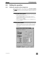

2.8 Suppressor module
761 Compact IC
43
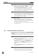
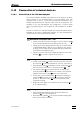
2.8.4 Connection of the suppressor module
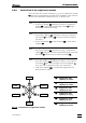
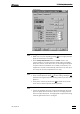
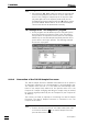
The three inlets and outlets numbered 1...3 on the suppressor module
47 each have 2 permanently mounted PTFE capillaries, which must be
connected as described as follows (see Fig. 16 and Fig. 18).
1 Inlet capillary for eluent
• Screw inlet capillary 96 marked with "Eluent" of suppressor
module 47 to outlet end of separating column 81 using a
6.2744.010 Compression fitting.
2 Outlet capillary for eluent
• Screw outlet capillary 97 marked with "Detector" of suppres-
sor module 47 to coupling 33 using a 6.2744.010 Compres-
sion fitting.
• Screw inlet capillary 45 of detector block 46 to other end of
coupling 33.
3 Inlet capillary for H
2
SO
4
• Attach inlet capillary 99 marked with "H
2
SO
4
" of suppressor
module 47 using a 6.2744.010 Compression fitting to the filter
unit PEEK 36 connected to the rear pump tubing 92.
4 Outlet capillary for H
2
SO
4
• Pull outlet capillary 101 marked with "Waste" of the suppres-
sor module 47 from below through one of the openings 13
out of the inner compartment of the 761 Compact IC.
• Lead outlet capillary 101 to a sufficiently large waste con-
tainer and fix it in place.
1
3
2
96
100
98
9799
101
Fig. 18
: Connections at suppressor module
96
Suppressor inlet
capillary for eluent
97 Suppressor outlet
capillary for eluent
98 Suppressor inlet
capillary for H
2
O
99 Suppressor inlet
capillary for H
2
SO
4
100 Suppressor outlet
capillary for H
2
O
101 Suppressor outlet
capillary for H
2
SO
4
Eluent
H
2
O
Detector
Waste
Waste
H
2
SO
4