
Owner manual

2.8 Suppressor module
761 Compact IC
39
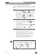
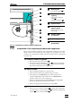
• Press contact pressure lever 49 on both tubing cartridges
down as far as it will go.
• Insert the pump tubings 92 and 93 (6.1826.060) into each of
the tubing cartridges as shown in Fig. 15. The white-yellow
stopper 94 must click into the corresponding holder on the
left-hand side of the tubing cartridge.
• Place the tubing cartridges on mounting pin 53 and press
down on the right-hand side until snap-action lever 51 clicks
into position on holding clamp 50. Take care that no kinks are
formed in the pump tubing.
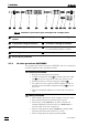
2 Install Filter units PEEK
• Mount a coupling 91 (6.2744.030) to the outlet end of the two
Pump tubings 92 and 93.
• Attach a piece of PTFE tubing 95 (6.1803.020) cut to the
required length (normally ca. 10 cm) using a compression
fitting 54 (6.2744.010) to the other end of this coupling.
• Attach the PTFE tubing 95 using a compression fitting 54
(6.2744.010) to the filter-screw 57 of the filter unit PEEK (see
section 2.3.6).
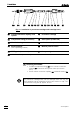
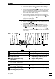
89/90 91 92/93 94 48 49 94 91 98/9951 5454 95 54 59 57 54
Fig. 15
: Installing pump tubings
48
Tubing cartridge 91 Coupling (6.2744.030)
49 Contact pressure lever 92 Pump tubing (6.1826.060) for H
2
SO
4
51 Snap-action lever 93 Pump tubing (6.1826.060) for H
2
O
54 PEEK compression fitting
(6.2744.010)
94 Stopper (white-yellow)
57 Filter-Screw of Filter Unit
Part of 6.2821.120 Filter unit
95 PTFE tubing (6.1803.020)
59 Filter-Housing of Filter Unit
Part of 6.2821.120 Filter unit
98 Suppressor inlet capillary for H
2
O
89 Aspirating tubing for H
2
O 99 Suppressor inlet capillary for H
2
SO
4
90 Aspirating tubing for H
2
SO
4