
Owner manual

6 Appendix
761 Compact IC
192
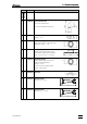
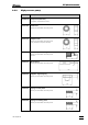
6.1.9 Remote interface
Connector Dsub 25 pin (female)
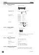
Circuit diagram for
output lines 1
…
8
Assignment of
output lines 1
…
8
Remote 1 Pin 18
Remote 2 Pin 4
Remote 3 Pin 3
Remote 4 Pin 1
Remote 5 Pin 2
Remote 6 Pin 16
Remote 7 Pin 17
Remote 8 Pin 5
Potentials
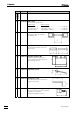
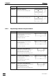
6.1.10 Analog output
Connector Dsub 9 pin (male)
Pin assignment 0 V
Measurement signal (0...1 V for set Full Scale
range 50, 250 or 1000 µS/cm)
Accuracy ± 1 %
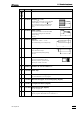
6.1.11 Mains connection
Voltage 115 V: 100...120 V ± 10 %
230 V: 220...240 V ± 10 %
Frequency 50...60 Hz
Power consumption 100 VA
Fuse 5 mm dia., 20 mm length
100…120 V: 1.0 A (slow-blow)
220…240 V: 0.5 A (slow-blow)
6.1.12 Safety specifications
Construction/testing According to IEC 1010 / EN 61010 / UL 3101-1,
protection class 1, degree of protection IP20
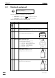
Pin
Remote
Pin 25
Pin 14
Pin 15
0V
+5V