
Owner manual

5 Notes – Maintenance – Faults
761 Compact IC
184
3 Clean suppressor rotor
• Clean the sealing surface of new suppressor rotor 127
(6.2832.000) using a lint-free cloth and ethanol.
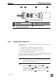
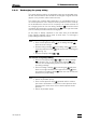
4 Insert suppressor rotor
• Insert new suppressor rotor 127 in suppressor holder 128 in
such a way that the tubing connections at the rear of the rotor
fit in the corresponding openings inside the rotor and that one
of the three holes in the rotor can be seen from below in one
of the openings of the holder.
• If the rotor has been inserted correctly, its sealing surface will
be about 4 mm inside the holder. If this is not the case, bring
the rotor into the correct position from below with the aid of a
sharp object (e.g. a screwdriver).
5 Clean connection piece
• Clean the sealing surface of new connection piece 126
(6.2832.010) with the aid of a lint-free cloth and ethanol.
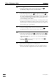
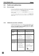
6 Insert connection piece
• Insert new connection piece 126 in suppressor holder 128 in
such a way that connection "1" is at the top and that the three
lugs on the connection piece fit in the corresponding open-
ings of the holder.
• Screw nut 125 onto the thread of suppressor holder 128
manually (do not
use tools).
7 Connect and condition the suppressor
• Reconnect the suppressor to the IC system.
• Before switching the suppressor to the next position for the
first time, rinse all 3 suppressor units with solution for 5 min.