
Owner manual

5.2 Maintenance and servicing
761 Compact IC
183
128127126125
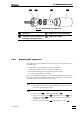
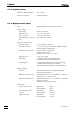
Fig. 22
: Assembling the suppressor
125
Screw nut 127 Suppressor rotor (6.2832.000)
126 Connection piece (6.2832.010)
with input and output leads
128 Suppressor holder
5.2.9 Replacing the suppressor
The suppressor in the suppressor block may have to be replaced in the
following cases:
• Irremediable loss of suppressor capacity (reduced
phosphate sensitivity and/or strong rise in baseline)
• Irremediable blockage of the suppressor (the suppres-
sor can no longer deliver solutions)
Both the 6.2832.000 Suppressor rotor and the 6.2832.010 Connection
piece with the input and output leads can be replaced. To replace these
components proceed as follows (see Fig. 22):
1 Disconnect suppressor from IC system
• Disconnect all input and output leads of the suppressor from
IC system and peristaltic pump.
2 Dismantle suppressor
• Unscrew nut 125 from suppressor holder 128.
• Pull out connection piece 126 and suppressor rotor 127 from
suppressor holder 128 (the connection piece and the rotor
normally stick together).
• Loosen connection piece 126 from suppressor rotor 127.