
Owner manual

5.2 Maintenance and servicing
761 Compact IC
181
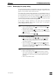
• Set the flow at the high-pressure pump to 0.5 mL/min and
rinse the suppressor unit with 1 mol/L H
2
SO
4
for 5 to 10 min.
• As the pressure falls, slowly increase the flow at the high-
pressure pump to 2 mL/min. Do not exceed a maximum
pressure of 2 MPa (20 bar).
• Switch off high-pressure pump.
• Switch suppressor to the next position using the
button.
• Connect the inlet capillary 98 marked "H
2
O" to the inlet capil-
lary 26 using coupling 33 (see Fig. 10 and Fig. 16).
• Set the flow at the high-pressure pump to 0.5 mL/min and
rinse the suppressor unit with 1 mol/L H
2
SO
4
for 5 to 10 min.
• As the pressure falls, slowly increase the flow at the high-
pressure pump to 2 mL/min. Do not exceed a maximum
pressure of 2 MPa (20 bar).
• Switch off high-pressure pump.
3 Connect suppressor to IC system
• Connect inlet capillaries 98 and 99 to the peristaltic pump
(see section 2.8.4).
• If the pressure problems persist, replace the suppressor rotor
(see section 5.2.9).
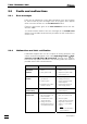
5.2.8 Cleaning the suppressor
It may be necessary to clean the suppressor in the following cases:
• High counterpressure on the suppressor connection
tubing
• Irremediable blockage of the suppressor (the suppres-
sor can no longer deliver solutions)
• Irremediable obstruction of the suppressor (the sup-
pressor can no longer be switched to next position)
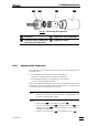
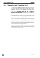
To clean the connection piece and the rotor, proceed as follows (see
Fig. 22):
1 Disconnect suppressor from IC system
• Disconnect input capillary 96 of the suppressor module 47
from the separating column 81 (see Fig. 16).
• Disconnect output capillary 97 from inlet capillary 45.
• Disconnect inlet capillaries 98 and 99 from the filter units 96
(supply from peristaltic pump).