
Owner manual

4.4 Methods
761 Compact IC
133
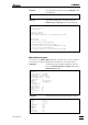
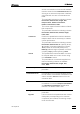
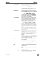
Channel table Parameters of the data acquisition channel
used.
CHANNELS TABLE
Cond
No Name Units Input Minimum Zero Maximum Range Coefficient Noise Shift
1 Cond uS/cm 1 -8388607 0 8388607 8.389e+01 1.000e-05 5.63 0
# Name/Units Noise RMS PeakToPeak Drift/hour
1 Cond 5.6 63047.3 796371.8 15119.570
uS/cm 5.63e-05 0.63 7.96 0.151
Name
Channel’s name. This text appears as Channel
label
in the chromatogram.
Units Units of detector response (µS/cm).
Input Number of data acquisition channel.
Minimum Minimum value of the linear range of the AD
converter (in ADC conversion units). This pa-
rameter is used to detect an underflow condi-
tion.
Zero A signal level on a baseline (in ADC conversion
units). This parameter is a result of the ADC
calibration.
Maximum Maximum value of the linear range of the AD in-
terface (in ADC conversion units). This parame-
ter is used to detect overflow condition.
Range An input signal value in maximum in µS/cm.
Range = (Maximum - Zero) • Coef
Coef ADC sensitivity coefficient (weight of ADC bit in
µS/cm).
Noise Estimated baseline noise value of the channel
in ADC conversion units (bits).
Shift Not used for 761 Compact IC.
Report destination
The following output devices can be selected simultaneously in any
combination as targets for report output:
Screen Output report (without curves) to screen.
Printer Output report to printer.
File Output report to file (see File output options).