760 Sample Changer Instructions for Use 8.760.
CH-9101 Herisau/Switzerland Phone +41 71 353 85 85 Fax +41 71 353 89 01 E-Mail info@metrohm.ch Internet www.metrohm.ch 760 Sample Changer Instructions for Use 8.760.1013 2000.
Table of Contents Page 1 OVERVIEW .................................................................1 1.1 Side View .................................................................... 1 1.2 Rear View .................................................................... 2 1.3 Sensors ...................................................................... 3 2 INSTALLATION ............................................................4 2.1 Setting up the Instrument ...........................................
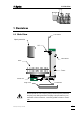
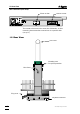
1.1 Side View 1 Overview 1.1 Side View Line frame Splash protection Lift Line sleeve Rack Tower Stirrer rail Plug cover Connectors Safety note: Never operate the 760 Sample Changer without splash protection and plug cover being mounted. The plug cover prevents any contamination of the connectors, caused by spilled solvents or chemicals.
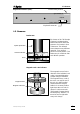
1.2 Rear View The Connectors (side view): Stirrer sockets Remote socket The remote socket serves the connection of Metrohm- or other measuring instruments that communicate via a parallel cable (see p. 11). 1.2 Rear View Line frame Mounting srew for splash protection Line sleeve Plug cover Type 1.760.0010 Nr.
1.3 Sensors Manufacturing number Keyboard Connector (rear): Type 1.760.0010 Nr. 0010/01104 Keyboard Made by Metrohm Herisau Switzerland Keyboard connector 1.3 Sensors Beaker test Each tower of the 760 Sample Changer is equipped with a beaker indicator to detect the presence of a beaker in front of the tower. This infrared sensor detects many different materials, if any object is placed in correct position. This beaker test is carried out after each MOVE operation.
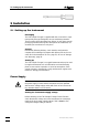
2.1 Setting up the Instrument 2 Installation 2.1 Setting up the Instrument Packaging The 760 Sample Changer is supplied with the accessories in separate special packages designed to ensure maximum protection. These contain shock-absorbing foam linings. As only these special packages guarantee damage-free transport of the instrument, it is essential you store them in a safe place.
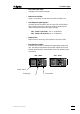
0 Power Supply • Disconnect line cable Unplug the 760 Sample Changer. • Remove fuse holder Using a screw driver, loosen the fuse holder and pull it out. • Checking and replacing fuse Carefully remove the built-in fuse and check its specifications. (The position of the fuse in the fuse holder is marked by the white arrow printed next to the supply voltage): 100… … 120 V 0.5 A (slow) ord. no. U.600.0014 220… … 240 V 0.25 A (slow) ord. no. U.600.
2.2 Safety Considerations 2.2 Safety Considerations Safety note: Never operate the 760 Sample Changer without splash protection and plug cover being mounted. The plug cover prevents any contamination of the connectors, caused by spilled solvents or chemicals. If failure or malfunctioning occurs during operation of the 760 Sample Changer, the Metrohm Service Department should be consulted.
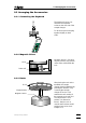
2.3 Arranging the Accessories 2.3 Arranging the Accessories 2.3.1 Connecting the Keyboard The keyboard is to be connected to the keyboard socket on the rear side of the sample changer. Type17 .600 .010 Nr. 0010/01104 Keyboard MadebyMetrohmHerisauSwitzerland To disconnect press the plug together slightly on both sides. 2.3.2 Magnetic Stirrer Rack Magnetic stirrers 2.741.0010 may be placed in any position on the stirrer rail beneath the rack. Stirrer rail 2.3.
2.3 Arranging the Accessories 2.3.4 Mounting and Setting up the Titration Heads Macro Titration head 6.1458.010 Micro Titration head 6.1458.020 Mounting screws M8 Aspiration tip (also for Macro Titration head) 6.1543.170 Electrode Rotating nozzle 6.2740.000 Burette tip 6.1543.200 Rod stirrer 2.722.0020 M6 Spray nozzles (also for Macro-Titration head) 6.2740.020 SGJ14 sleeve 6.1236.020 M8 Thread stopper 4.658.0180 SGJ9 Guide sleeve 6.2709.070 Stirrer propeller 6.1909.
2.3 Arranging the Accessories Mounting and Setting up the Titration head KFT Titration head KFT 6.1458.030 Mounting screws Double-Pt-Electrode 6.0340.000 Burette tips 6.1543.200 M10 Thread connectors 6.1543.200 O-Rings E.301.0022 O-Ring (bottom side) E.301.0080 Note: For an optimal sealing of the titration vessel, the M10 thread connectors should be mounted together with the O-rings.
2.3 Arranging the Accessories 2.3.5 Use of the Sample Beaker for Karl Fischer Titration Foil holder 6.2037.040 Al foil For Karl Fischer titration the weighted sample is dosed into the sample beaker together with a stirring bar 6.1903.010. The beaker is sealed with a centered aluminium foil 6.2820.000 using the foil holder. Sample beaker During the method run the lift is moved down to the working position. Thereby, the electrode and burette tips break through the Al foil. Using Al foil 6.2820.
2.4 Remote Connections 2.4 Remote Connections 765 776 Dosimat Remote Titrino Family 702 716 718 719 720 736 751 758 784 785 Valves 760 Sample Changer Relay Box 731 Pumps, e.g. 772 Connecting peripheral instruments to the 760 Sample Changer requires Metrohm cables. Otherwise a safe data transmission may not be guaranteed. The required cables are listed in the following table. Details about the control commands are given in the Instructions for Use of the corresponding instrument.
2.4 Remote Connections 14 lines (Output 0–13) are available for the emission of signals. For receiving signals 8 lines are provided (Input 0–7). The assignment of these lines is fixed for the 760 Sample Changer.
2.4 Remote Connections 760 Sample Changer — Titrino — Dosimat 765/776 A B Titrino A 765 D C B D C Cable 6.2141.040 Remote control commands: Output 0: Output 6: Input 3: *************1 *******1****** ****1*** starts Titrino starts Dosimat awaits end of titration (EOD pulse) Pump Control via Remote Lines Using methods 3 and 4, external pumps can be controlled via the remote interface.
2.5 Racks 2.5 Racks A sample rack is a sort of turntable for the positioning of beakers which are to be placed on the Sample Changer. Because for titration, various sizes of beakers are common or required, many kinds of racks can be used and are easily interchangeable. The rack offers space for various numbers of samples depending on the diameter of the beakers.
3.1 Important Features 3 Introduction 3.
3.2 Key Functions 3.2 Key Functions The 760 Sample Changer operates in two different modes where the keys provide different functions: The Basic Mode starts when the instrument is turned on. The ready-to-operate status is indicated by the green LED. Basic Mode: (after Power on, green LED on) START RESET Starts processing of a sample series. STOP Stops processing of a sample series or initializes the 760 Sample Changer. HOLD Interrupts processing of a sample series, green LED blinks.
3.3 Memory Initialization 3.3 Memory Initialization The system memory can be initialized to set default parameters when required (e.g. in the case of mal-functions). For this purpose press all keys while the sample changer is switched on. It is recommended to execute an initialization before the first installation of the sample changer. RESET START HOLD STOP and "Power on" 3.
3.4 Configuration Procedure The Configuration Procedure Key LEDs Explanation In order to start the configuration procedure the key must be pressed while the sample changer is switched on. The green LED lights up once to show that the configuration procedure is active. The method can now be selected. HOLD + "Power ON" green 1∗ red 1-4∗ HOLD green 1∗ START When the key is pressed the red LED blinks once for the first method.
3.4 Configuration Procedure red blinks HOLD green 5∗ The key switches on the stirrer(s). If the key is kept pressed down the speed increases continuously. If the key is pressed again the stirrer speed is reduced in a similar manner. In this way the stirrer speed can be set accurately. accepts the setting. The configuration procedure is now complete. It can be restarted by pressing in order to select the method.
3.5 The Methods 3.5 The Methods All methods enable the dosing of auxiliary solutions before the titration if a 765 or a 776 Dosimat is used. The dosing volume is to be defined in the Dosimat. The Sample Changer will start the distribution via a remote line. The following titration instruments can be used with the 760 Sample Changer: all of the Titrino models (701, 702, 716, 718, 719, 720, 736, 751, 758, 784, and 785) and the Titroprocessors.
3.5 The Methods Method 2 (for exact sequence, see Appendix, p. 26) Working procedure with sensor conditioning by dipping. The special beaker (highest rack position) must be filled before with solvent or water. Procedure: 1. 2. 3. 4. 5. 6. 7. 8. 9. 10. 11. 12. 13.
3.5 The Methods Method 4 (for exact sequence, see Appendix, p. 28) Working procedure with sensor rinsing in the sample beaker using an external pump. Procedure: 1. 2. 3. 4. 5. 6. 7. 8. 9. 10. 11. 12.
4.1 Error Messages 4 Appendix 4.1 Error Messages An error occurring during a sample series is displayed by a blinking red LED. The number of flashes indicates the error number. This must be acknowledged with any key. If an error occurs during processing of a sample series, the changer will then be switched into the 'HOLD' state. After the cause of the error has been rectified, the sample series can be continued with the next command in the active sequence by pressing the key.
4.1 Error Messages 24 9* missing beaker After a MOVE command no beaker could be found at the selected position. 10* raise lift first Turning of a rack could not be carried out because a lift was below the defined shift position. 12* changer overload Load or resistance too large to carry out the chosen action. 14* changer not ready The changer cannot execute the command chosen because it is busy carrying out another action.
4.2 Method Listings 4.2 Method Listings All four methods of the 760 Sample Changer are briefly described in chapter 3.5 on pages 20 to 22. The present chapter contains the exact program listings of these methods together with more detailed explanations. Method 1 760 Sample Changer 760.
4.2 Method Listings Method 2 760 Sample Changer 760.
4.2 Method Listings Methode 3 760 Sample Changer 760.
4.2 Method Listings Methode 4 760 Sample Changer 760.
4.3 Technical Specifications 4.3 Technical Specifications Dimensions Height: 0.79 m, Width: 0.28 m, Depth: 0.48 m Weight 12.5 kg Material Sample Changer case: Splash protection: Sample rack: Lift path 235 mm Lift Load: Stroke speed: Turntable Turning speed: 20 angular degrees/s Stirrer Stirring rate: adjustable to 15 levels - magnet stirrer 180/min...2600/min - rod stirrer 180/min...
4.4 Servicing and Maintenance Electromagnetic Compatibility (EMC) Emitted Interference: The instrument complies with the basic specifications EN 50081-1/2 1992, EN 55011 (class B), EN 55022 (class B). Interference immunity: The basic specifications EN 50082-1 1997, and IEC 801-2 to IEC 801-4 are adhered to. 4.4 Servicing and Maintenance 4.4.1 Servicing The maintenance of the 760 Sample Changer should include a yearly service check carried out by a specialist from Metrohm.
4.5 Warranty and Conformity 4.5 Warranty and Conformity 4.5.1 Warranty The warranty on our products is limited to defects that are traceable to material, construction or manufacturing error which occur within 12 months from the day of delivery. In this case, the defects will be rectified in our workshops free of charge. Transport costs are to be paid by the customer. For day and night operation, the warranty is limited to 6 months.
4.5 Warranty and Conformity 4.5.2 Certificate of Conformity and System Validation for the 760 Sample Changer This is to certify the conformity to the standard specifications for electrical appliances and accessories, as well as to the standard specifications for security and to system validation issued by the manufacturing company. Name of commodity: System software: Name of manufacturer: Principal technical information: 760 Sample Changer Stored in ROMs Metrohm Ltd.
4.5 Warranty and Conformity Ionenanalytik • Analyse des ions • Ion analysis • Análisis iónico 760 Sample Changer EU Declaration of Conformity The Metrohm AG company, Herisau, Switzerland hereby certifies that the instrument: 760 Sample Changer meets the requirements of EU Directives 89/336/EWG and 73/23/EWG.
4.6 Accessories 4.6 Accessories 760 Sample Changer includes the following accessories: SGJ14 sleeve FEP tubing connector M6 80cm Spiral band 7x0,75 0,5m Keyboard for 760 Guiding sleeve Splash protection Plug cover Instructions for use 760 Sample Changer KFT includes the following accessories: Magnetic stirrer Double Pt electrode Sample beaker Titration head for FKT FEP tubing connector M6 80cm Spiral band 7x0,75 0,5m Aspirating tube for 676 (Behr) Stirring bar 12mm Foil holder for beaker 6.1432.
4.6 Accessories Options Accessories to separate order at additional charge: 722 Propeller Rod Stirrer for Sample Changer Propeller rod stirrer Stirring propeller PP (104 mm) (incl.) 2.722.0020 6.1909.020 741 Magnetic Stirrer Magnetic stirrer 2.741.0010 Macro titration head (6 x SGJ 14, 3 x SGJ 9) Micro titration head (4 x M10) for rack 6.2041.340 6.1458.010 6.1458.
4.6 Accessories Electrodes for sample changer For titrations with the macro titration head it is advisable to use long life LL electrodes. Titrodes without standard ground joint should be used with the SGJ sleeve 6.1236.040 made of silicone rubber.
5 Index 5 Index A K Accessories...................... 34 Aluminium foil................... 10 Appendix.......................... 23 Aspiration tip ...................... 8 Key functions.................... 16 Keyboard connector............ 3 KF sample beaker............. 10 KF titration head ................. 9 B L Basic mode ...................... 16 Basic settings ................... 15 Battery............................. 23 Beaker test......................... 3 Burette tip ......................