CH-9101Herisau/Switzerland Tel. ++41 71 353 85 85 Fax ++41 71 353 89 01 Internet www.metrohm.ch E-Mail info@metrohm.ch 751 GPD Titrino Series 9... Instructions for Use 8.751.1103 99.
Table of contents Table of contents 1 Overview................................................................................................................... 1 2 Manual operation ..................................................................................................... 4 2.1 Keypad.......................................................................................................................... 4 2.2 Principle of data input..............................................................
Table of contents 3 Operation via RS232 Interface (green pages)...................................................... 105 3.1 General rules ............................................................................................................ 105 3.1.1 Call up of objects............................................................................................... 106 3.1.2 Triggers.............................................................................................................. 107 3.1.
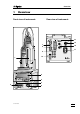
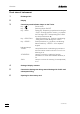
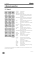
Overview 1 Overview Front view of instrument: Rear view of instrument: 14 Remote 1.751 Nr.
Overview Front view of instrument: 1 Exchange Unit 2 Display 3 Control keys and indicator lamps on the Titrino Key < > Power switch Key < 4 > Key Key Key Indicator lamps: "COND." "STATISTICS" "SILO" 2 Switching stirrer ON/OFF Dosing key. Dispensing is performed as long as is being pressed. Used e.g. to prepare the Exchange Unit. The dispensing rate can be set with potentiometer (5). - Stops procedures, e.g. titrations, conditioning.
Overview Rear view of instrument: 7 RS232 interfaces 2 separate interfaces for the connection of printer, balance, and computer 8 Remote lines (input/output) for the connection of the Remote Box, Sample Changers, robots etc. 9 Connection of electrodes and temperature sensor • 2 high-impedance measuring inputs for pH and U measurements. They can either be used separately or for differential potentiometry, see page 215.
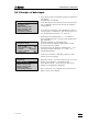
2.1. Keypad 2 Manual operation 2.1 Keypad PARAM EP MEAS/HOLD + SILO 8 9 RS CAL.DATA * CARD DEF USER METH ) CONFIG STATISTICS 7 PREP 4 C-FMLA C 1 PRINT 0 CONFIG PARAM SMPL DATA STATISTICS SMPL DATA MN 5 ( 2 6 MODE . – USER / 3 REPORTS ABC – ; CURVE ← ↑ → CLEAR ↓ ENTER STOP QUIT START 6.2132.060 Configuration. Parameters. Sample data. ON/OFF switching of statistics calculations of consecutive determination, see page 77.
2.2 Principle of data input 2.2 Principle of data input configuration >monitoring >peripheral units >auxiliaries >RS232 settings COM1 >RS232 settings COM2 >common variables >prep.dosing elements configuration >peripheral units send to COM1: IBM send to COM2: IBM man.reports to COM: 1 balance: Sartorius stirrer control: OFF remote box: OFF • If you press a key you will find a group of inquiries in the display.
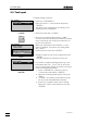
2.3. Text input 2.3 Text input Example storing a method: user methods >store method method name: ******** • Delete this name with . REPORTS . ABC user methods >store method: method name: ABCDEFGHIJKLMNOPQRSTUVWXYZ abcdefghijklmnopqrstuvwxyz µ°!"#$&'()*+,-./ 0123456789 user methods >store method method name: 6 • Press key . Place the cursor to ">store method" and press . The name of the method which is currently in the working memory is displayed.
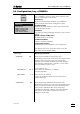
2.4 Configuration, key 2.4 Configuration, key Key serves to enter device specific data. The set values apply to all modes. monitoring: Monitoring of instrument validation, pH calibration, service interval and printout of diagnostic report. peripheral units: Selection of printer, balance, stirrer control and COM for manual report output. auxiliaries: e.g. setting of dialog language, date time, type of result display. RS232 settings COM1 and 2: RS parameters for the COM's.
2.4. Configuration, key meas.input: time interval time counter 1 7 d 0 d service: next service OFF YYYY-MM-DD system test report: OFF send to COM1: IBM send to COM2: IBM man.reports to COM: 8 Monitoring the service interval (ON, OFF) Monitoring is carried out after the Titrino has been switched on. If the monitoring responds the message "Service is due" appears. The message vanishes with .
2.4 Configuration, key stirrer control: OFF remote box: OFF keyboard: barcode: US input english date 1998-04-23 time 08:13 run number 0 auto start OFF 751 GPD Titrino Connection of a remote box (on ,OFF) To the remote socket for PC keyboard and barcode reader, see page 212. If "on" has been set: Type of PC keyboard (US, German, French, Spanish, Swiss.) The PC keyboard is used as an input aid, see page 213.
2.4. Configuration, key start delay 0 s result display: bold 751.0020 baud rate: Display of program version Settings of RS232 interface see also page 180. Identical for COM2. >RS232 settings COM1 9600 Baud rate (300, 600, 1200, 2400, 4800, 9600, 19200, 38400, 57600, 115200) data bit: 8 Data bit (7, 8) stop bit: 1 Stop bit (1, 2) parity: handshake: none HWs C30 etc. Parity (even, odd, none) Handshake (HWs, SWline, SWchar, none) see page 180.
2.4 Configuration, key dos.element: internal D0 Selection of the dosing element (internal D0, external D1, external D2) internal D0: buret of the Titrino external D1/2: buret D1, D2, resp. warn.interv.DX OFF min Warning interval for prep (5...9999 min, OFF) dos.drive: Dosimat Selection of the type of dosing element (Dosimat, Dosino) The internal buret D0 reacts like a "Dosimat". volume DX 3.
2.4. Configuration, key Settings with key and power ON Proceed as follows: 1. Switch the Titrino OFF. 2. Press and keep it pressed during switching the Titrino ON. The display shows the following: 12 Setup >lock >curve lock: Locking keys , and , and the functions "recall method", "store method" and "delete method" of the internal method memory in the Titrino. curve: Changes the appearance of the curve printout.
2.4 Configuration, key curve The settings are valid for COM1 and COM2. If you change the printer type, the following settings are initialized according to the printer. >curve grid: ON Grid drawing (ON, OFF) frame: ON Frame drawing (ON, OFF) scaling: Full Type of scaling (Full, Auto) Full: The scaling goes from the greatest to the smallest value. auto: The scaling from tick to tick, e.g. the smallest/greatest values lie in between the first/last tick. width 0.75 Width (0.2...1.
2.5. Selection of the mode, key 2.5 Selection of the mode, key MODE – Press key until the desired mode is displayed and confirm with . Select the measured quantity pH, U, Ipol, Upol, (T) with <←> or <→> and confirm it also with . ; mode mode: measured quantity: DET pH The following modes can be selected: • DET: Dynamic Equivalence-point Titration • MET: Monotonic Equivalence-point Titration • SET: Set Endpoint Titration.
2.6 Parameters, key 2.6 Parameters, key The key is used for the entry of values that determine the modes. Values marked with "cond." are accessible during the conditioning in the SET and KFT mode. "**titr." means that these values can be changed during the titration. They influence the ongoing determination. Other values can only be changed in the inactive state. The display texts of the Titrino are shown to the left. The values are the default values. PARAM 2.6.
2.6. Parameters, key dos.rate **titr. signal drift **titr. equilibr.time **titr. start V: start V factor dos.rate **titr. 16 Dosing rate for volume increments (0.01...150 mL/min, max.) sets "max.". The maximum rate depends on the Exchange Unit: Exchange Unit max. 5 mL 15 mL/min 10 mL 30 mL/min 20 mL 60 mL/min 50 mL 150 mL/min max. ml/min 50 mV/min Drift criterion for measured value acquisition. (input range depends on the measured quantity: pH, U, Ipol: 0.5...
2.6 Parameters, key pause **titr. 0 s Waiting time (0...999 999 s) Waiting time, e.g. for equilibration of the electrode after the start or reaction time after dosing of start volume. The pause can be aborted with . dos.element: internal D0 Selection of the dosing element (internal D0, external D1, external D2) internal D0: internal buret of the Titrino external D1/2: buret D1, D2, resp. meas.input: Measuring input for pH and U (1, 2, diff.) Request for measuring input for pH and U.
2.6. Parameters, key stop pH **titr. stop EP **titr. OFF 9 filling rate max. ml/min **titr. Stop after a number of EP's have been found (1...9, OFF) sets "OFF". "OFF" means that the criterion is not monitored. Filling rate (0.01...150 mL/min, max.) sets "max.". The maximum rate depends on the Exchange Unit: Exchange Unit max. 5 mL 15 mL/min 10 mL 30 mL/min 20 mL 60 mL/min 50 mL 150 mL/min EP evaluation/recognition See page 21 ff.
2.6 Parameters, key sets "OFF". Only equivalence points are recognized which lie within the set lower and upper limits. The equivalence point numbering is defined with the windows, see page 23. Window inquiries continue until the lower limit is set to "OFF". Up to 9 possible windows. Always set both limits to ≠ OFF for a valid window. fix EP1 at pH OFF Interpolation of volumes at fixed times (input range depends on the measured quantity: pH: 0...±20.00, OFF U, Ipol: 0...
2.6. Parameters, key Titration sequence of DET and MET (Activate pulse) (Stirrer ON) (Start delay) (Request ident.) (Request smpl size) The start delay time is waited off. The sample identifications and the sample size are requested. (Start conditions) The start volume is dispensed (no meas.value acquisition) and the pause is waited off. Titration: Dispense increments Acquire meas.
2.6 Parameters, key Reagent feeding and EP evaluation of DET The reagent feeding of DET is similar to the controlling, a human being would apply in manually controlled titrations: Great volume increments are dosed far away from the EP, small increments in the region of the equivalence point. The size of the volume increments dosed by the Titrino is determined by the following parameters: meas.pt.density min.incr. The measuring point density is entered as a relative value from 0...9.
2.6. Parameters, key Reagent feeding and EP evaluation of MET In monotonic titrations, the volume increment is constant over the whole titration curve. V step Volume increment. A prerequisite for good accuracy is the correct size of the volume increments. A good value is given by V step = 1/20 VEP (VEP = volume of the EP).
2.6 Parameters, key EP recognition criteria for DET and MET The parameter "EP recognition" offers you a range of possibilities to ensure selection of the EP you are interested in: If the desired jump is very large, you can select the "greatest" jump (with DET the steepest jump will be evaluated). Thus you always obtain just one EP per titration (EP1). If you wish to determine the sum of different components (e.g. acid or base numbers), the "last" jump can be the correct one.
2.6. Parameters, key Fix EP's Fix EP's allow determination of the associated volume value for every inputted measured value on the titration curve. This function is useful for performing standard methods such as TAN/TBN determinations. For the evaluation of fix EP's, the pH calibration is advisable. The volume values of the fix EP's are available for the calculation as C5X: Fix EP1 ⇒ C51 : Fix EP9 ⇒ C59 Maximum 9 fix EP's are possible.
2.6 Parameters, key 2.6.2 Parameters for SET parameters >SET1 >SET2 >titration parameters >stop conditions >statistics >preselections SET1, SET2: Control parameters for EP1 and EP2. titration parameters are valid for the global titration sequence. stop conditions: Parameters for the termination of the titration. statistics: Calculation of mean values and standard deviation, see page 77.
2.6. Parameters, key min.rate **titr. Minimum dosing rate (0.01...999.9 uL/min) This parameter determines the addition rate right at the start and the end of the titration, see also page 31. This parameter influences the titration speed and therefore its accuracy very strongly: A smaller min.rate results in a slower titration. 25.0 ul/min stop crit: **titr. stop drift **titr. Type of stop criteria (drift, time) drift 20 ul/min t(delay) **titr. 10 s stop time **titr.
2.6 Parameters, key dos.rate **titr. max. ml/min Dosing rate for start volume (0.01...150 mL/min, max.) sets "max.". The maximum rate depends on the Exchange Unit: Exchange Unit max. 5 mL 15 mL/min 10 mL 30 mL/min 20 mL 60 mL/min 50 mL 150 mL/min pause 2 **titr. 0 s Pause 2 (0...999 999 s) Waiting time after start volume, e.g. reaction time after dosing of a start volume. The waiting time can be aborted with . extr.time **titr. 0 s Extraction time (0...
2.6. Parameters, key Stop conditions for titration If this is not "normal", i.e. after reaching the EP. >stop conditions stop V: **titr. abs. stop V **titr. 99.99 ml factor **titr. 999999 filling rate max. ml/min conditioning: OFF display drift: cond. 28 If "abs." is set: Absolute stop volume (0...9999.99 mL) If "rel." is set: Factor for relative stop volume (0...±999 999) Calculated as: Stop V in mL = factor * sample size Filling rate after the titration (0.01...150 mL/min, max.
2.6 Parameters, key req.smpl size: cond. OFF Request of sample size after start of titration (value, unit, all, OFF) "all" the value and the unit will be requested. limit smpl size: cond. OFF Limiting value check for sample size (ON, OFF) With "on" the error message "sample size out." appears if the entry is outside the set limits. The limiting values are shown in the display window. The absolute value of the limit is checked during sample size input and during the calculation of the results.
2.6. Parameters, key Titration sequence of SET (Activate pulse) (Stirrer ON) (Start delay) (Preconditioning) ( (Activate pulse) (Start delay) After the start, the activate pulse is outputted and the stirrer switched on. The start delay time is waited off. If conditioning is on, the sample solution is titrated until the (first) EP is reached. The display shows then drift OK 2.3 ul/min or SET pH conditioning The vessel is now conditioned. The titration can be started with .
2.6 Parameters, key Control parameters The control parameters can be set separately for each end point. Optimize your control parameters for routine analyses for samples with a rather low content. During the titration, reagent dosing occurs in 3 phases: U/mV EP 1. Initial dosing: Here the dosing rate increases constantly. The rate starts with "min.rate" and goes up to "max.rate". 2. Continuous dosing: Dosing is performed at the maximum rate "max.rate" until the control range (dynamics) is reached.
2.6. Parameters, key Relation between the stop criteria "time" and "drift" The stop criterion "time", t(delay), means that the end point must be exceeded for a certain period of time. In other words, after the last dosed increment, time t is allowed to elapse before the titration is stopped. The size of this last increment depends on the volume of the Exchange Unit used. With a 20 mL Exchange Unit, the smallest possible increment is 2 ul.
2.6 Parameters, key If you have entered the endpoint and the control range (dynamics), the default values for the other control parameters should suffice for the first titration. If you encounter difficulties in optimizing your titration, the following table will be of use. How to proceed if ... Problem Dosing at the end too long and with too small increments. "Never ends!" Possible causes and corrective measures • Increase "min.rate". Perform an experiment with a much higher min.rate.
2.6. Parameters, key 2.6.3 Parameters for KFT parameters >control parameters >titration parameters >stop conditions >statistics >preselections control parameters: for the EP. titration parameters control the general course of the titration. stop conditions: Parameters for the termination of the titration. statistics: Calculation of mean values and standard deviation, see page 77. preselections: ON/OFF of various auxiliary functions such as automatic requests after the start and activate pulse.
2.6 Parameters, key stop crit: **titr. stop drift **titr. Type of stop criteria (drift, time) drift 20 ul/min t(delay) **titr. 10 s stop time **titr. OFF s Titration stops if there is no dosing during t(delay) (0...999 s, INF) sets "INF" Switch off when EP is reached and the set time after the last dosing has elapsed. If "INF" = an inquiry for the stop time appears. Stop after a time (0...999 999 s, OFF) sets "OFF". Stop after the set time after start of titration.
2.6. Parameters, key pause 2 **titr. 0 s Waiting time after start volume (0...999 999 s) Second waiting time, e.g. reaction time after dosing of a start volume. The waiting time can be aborted with . extr.time **titr. 0 s Extraction time (0...999 999 s) During the extraction time no dosing occurs but the titration does not stop. The extraction time can be aborted with . dos.
2.6 Parameters, key Stop conditions for titration If this is not "normal", i.e. after reaching the EP >stop conditions stop V: **titr. abs. stop V **titr. 99.99 ml factor **titr. 999999 filling rate max. ml/min conditioning: ON display drift: cond. ON drift corr: cond. OFF drift value cond. 0.0 ul/min 751 GPD Titrino If "abs." is set: Absolute stop volume (0...9999.99 mL) If "rel." is set: Factor for relative stop volume (0...
2.6. Parameters, key req.smpl size: cond. OFF Request of sample size after start of titration (value, unit, all, OFF) "all" the value and the unit will be requested. limit smpl size: cond. OFF Limiting value check for sample size (ON, OFF) With "on" the error message "sample size out." appears if the entry is outside the set limits. The limiting values are shown in the display window. The absolute value of the limit is checked during sample size input and during the calculation of the results.
2.6 Parameters, key Titration sequence of KFT (Activate pulse) (Stirrer ON) (Start delay) (Preconditioning) ( (Activate pulse) (Start delay) After the start, the activate pulse is outputted and the stirrer switched on. The start delay time is waited off. If conditioning is on, the sample solution is titrated until the EP is reached. The display shows then drift OK 2.3 ul/min or KFT conditioning The vessel is now conditioned. The titration can be started with .
2.6. Parameters, key Control parameters for KFT The control parameters can be set according to your samples. The default parameters are already set to get satisfactory results. Optimize the control parameters for specific samples only. During the titration, reagent dosing is carried out in 3 phases: U/mV 1. Initial dosing: Here the dosing rate increases constantly up to "max.rate". KFT Ipol EP V/ml t/s V/ml Initial dosing Continuous dosing 2.
2.6 Parameters, key Mechanisms of the KFT parameters in Ipol mode U/mV + Excess H2O Titration (direct titration) EP at U Excess Iodine- Titration (Back titration) I(pol) darker solution + I/uA • The position and curve characteristics of the line between the ranges of excess water or excess iodine depends on the type of sample and the ingredients of the working media. • The endpoint has to be set close to the range margin, but always within the iodine excess range.
2.6. Parameters, key The determination of the free water is easily done, as far as the specifications of the reagent manufacturer regarding the "water capacity" of the reagents are considered. Problems may occur with specific sample matrices. The relevant literature contains many precise analysis instructions. In the following table we attempt to show you solutions related more to the instrument's side: What to do if ... Problem Dosing at end too long and increments too small.
2.6 Parameters, key 2.6.4 Parameters for STAT parameters >control parameters >titration parameters >stop conditions >statistics >evaluation >monitoring >preselections control parameters: for reaching the control point. titration parameters control the global course of the titration. stop conditions: Parameters for automatic termination of the titration. statistics: Calculation of mean values and standard deviation, see page 77. evaluation: Evaluation of rates, fix volumes and fix times.
2.6. Parameters, key min.rate **titr. Minimum dosing rate (0.01...9999 uL/min) This parameter determines the addition rate in the range of the control point. Rule of thumb for "min.rate" in uL/min = (expected rate of the reaction in uL/min)/10. 25.0 ul/min Titration parameters >titration parameters start V: start V 0.0 ml factor dos.rate **titr. 44 Type of start volume (OFF, abs., rel.) "OFF": start volume switched off "abs.": absolute start volume in mL "rel.
2.6 Parameters, key start rate OFF ml/min time interval 2 s Start rate for data acquisition (0.01...150 mL/min, OFF) sets "OFF". Measured values will be acquired only if the current rate is below the start rate. This criterion effective 10 s after the start. Time interval for data acquisition (1..999 999 s) Time interval for the entry of the values in the measuring point list. The measuring point list can contain max. 500 points.
2.6. Parameters, key Stop conditions The condition which is met first will be effective. >stop conditions stop time: **titr. stop time t(delta) t(delay) **titr. factor **titr. stop V: **titr. OFF 999999 s 999999 s 999999 s 999999 abs. stop V **titr. 99.99 ml factor **titr. 999999 stop rate **titr. OFF ml/min filling rate max. ml/min **titr. 46 Type of stop time (abs.,rel., delta, delay, OFF) "abs": absolute stop time in s "rel.": relative stop time to sample size.
2.6 Parameters, key Evaluation see also page 54. >evaluation low lim.1 up lim.1 OFF s OFF s Evaluation of dosing rates within time windows (0...999 999 s, OFF) Up to 9 time windows in which a rate should be calculated. The rates are available for calculations as C8X. For the calculation of a rate, the measuring point list in the time window must contain at least 4 points. If no point falls on the window limits, the next outer one is used.
2.6. Parameters, key rate: **titr. low lim. up lim. action: **titr. OFF 0.000 ml/min 150 ml/min none temperature: **titr. low lim. up lim. action: **titr. OFF -170.0 °C 500.0 °C none assign output L10: violated limit: output L10: none any pulse Monitoring of rate (ON, OFF) With "on" follow the requests: Limit values (0.000...150 mL/min) Action if a limit is exceeded (end, hold, wait, none) end: Abort. hold: Hold reagent addition until manually restarted.
2.6 Parameters, key Preselections for the sequence >preselections req.ident: OFF Request of sample identifications after start of titration (id1, id1&2, all, OFF) After start, sample identifications can be inquired automatically: Only id1, id1 & id2, all three id's or no inquiries. req.smpl size: OFF Request of sample size after start of titration (value, unit, all, OFF) limit smpl size: OFF Limiting value check for sample size (ON, OFF) With "on" the error message "sample size out.
2.6. Parameters, key Sequence for STAT (Activate pulse) (Stirrer ON) (Start delay) (Request ident.) (Request smpl size) The start delay time is waited off. The sample identifications and the sample size are requested. (Start conditions) The start volume is dispensed (without controlling or measured value acquisition and there is no monitoring during this time) and the pause is waited off.
2.6 Parameters, key Control parameters U/mV EP Control range V/ml t/s V/ml Dosing outside the control range: The dosing rate is given mainly by the parameter "max.rate". Optimize the parameters "max.rate" and "dynamics" together to avoid overtitration the first time the control point is reached. Set "dynamics" such that the measured value lies inside the control range during the phase where the value is kept. Set "dynamics" to e.g. pH=3, U=180 mV for slow reactions.
2.6. Parameters, key Stop times V/ml Last dosing Control point (EP) reached the first time t(delay) t(delta) stop time t/s Stop time: The stop time runs over the whole controlling time of the determination: It starts after dosing of the start volume and after the pause: The stop time can be absolute (in s) or relative to the sample size (time in s = factor * smpl size). 52 t(delta): t(delta) starts after controlling point (EP) has been reached the first time.
2.6 Parameters, key Measuring point list and monitoring General information on measuring point list: • Measured points are entered in the measuring point list at the preset time interval. • If one (or more) entries appear during the refilling time, one measured point is entered immediately after the refilling. The time reference otherwise remains unchanged, however.
2.6. Parameters, key Evaluation Rates C8X The rates are calculated by linear regression. C80 is the mean rate over all points of the measuring point list. C8X (9≤X>0) are the rates in the specified time windows. At least 4 points are necessary for an evaluation. If the limit of the time window does not coincide with a current measured point, the next outer is taken as the limit, see example below.
2.6 Parameters, key 2.6.5 Parameters for DOS parameters >dosing parameters >stop conditions >statistics >monitoring >preselections dosing parameters control the dosing stop conditions: Parameters for termination. statistics: Calculation of mean values and standard deviation, see page 77. monitoring of limit values for the measured value and temperature. preselections: ON/OFF of various auxiliary functions such as automatic requests after the start and activate pulse.
2.6. Parameters, key temperature 25.0 °C Stop conditions If a stop is not made after the dispensing time or after the dispensed volume. >stop conditions stop V: **titr. OFF stop V **titr. 99.99 ml factor **titr. 999999 56 If "rel." is set: Factor for relative stop volume (0...± 999 999) Calculated as: Stop V in mL = factor * sample size Monitoring of measured values Limit value violations are marked in the measuring point list.
2.6 Parameters, key I(pol) 1 uA U(pol) 400 mV electrode test: low lim. pH up lim. pH **titr -20.00 20.00 action: **titr. none temperature: **titr. low lim. up lim. action: **titr. OFF -170.0 °C 500.0 °C none assign output L10: violated limit: output L10: OFF none any pulse With polarized electrodes, the request of the measuring input is replaced by one regarding the polarization current (-127...127 uA), or the polarization voltage (-1270...
2.6. Parameters, key Preselections for the sequence >preselections req.ident: OFF Request of sample identifications after start of titration (id1, id1&2, all, OFF) After start, sample identifications can be inquired automatically: Only id1, id1 & id2, all three id's or no inquiries. req.smpl size: OFF Request of sample size after start of titration (value, unit, all, OFF) limit smpl size: OFF Limiting value check for sample size (ON, OFF) With "on" the error message "sample size out.
2.6 Parameters, key Sequence with DOS (Activate pulse) (Start delay) (Request ident.) (Request smpl size) After the start, the activate pulse is output. The start delay time is waited off. The sample identifications and the sample size are requested. (Pause) The pause is waited off. During this time the limits are not yet monitored. Dosing Acquisition of meas. (Monitoring) During the dosing, measured values (time, volume) are acquired and stored in the measuring point list.
2.6. Parameters, key Filling times Refilling times are not incorporated by the Titrino in the calculation of the rate. The filling times can be calculated using the following formula: max. filling rate filling rate in s = ÄÄÄÄÄÄÄÄÄÄÄÄÄÄÄ * 20 s + 3 s current filling rate The max. filling rate depends on the Exchange unit installed, see page 56. The filling times (incl.
2.6 Parameters, key Measuring point list and monitoring • Measured points are entered in the measuring point list at the preset time interval. The input times represent the clock time. This must be distinguished from the dispensing time: The dispensing time does not include any waiting times which can arise in refilling, hold or wait as a result of limit value violations. • If one (or more) entries occur in the time during refilling, one measured point is entered immediately after the refilling.
2.6. Parameters, key 2.6.6 Parameters for DOC parameters >dosing parameters >stop conditions >statistics >monitoring >preselections dosing parameters control the dosing stop conditions: Parameters for termination. statistics: Calculation of mean values and standard deviation, see page 77. monitoring of limit values for the measured value and temperature. preselections: ON/OFF of various auxiliary functions such as automatic requests after the start and activate pulse.
2.6 Parameters, key max.rate **titr. max. ml/min Maximum rate (0.01...150 mL/min, max.) sets "max.". This parameter primarily determines the addition rate outside the control range, see also page 68. The maximum rate depends on the Exchange Unit: Exchange Unit max. 5 mL 15 mL/min 10 mL 30 mL/min 20 mL 60 mL/min 50 mL 150 mL/min min.rate **titr. 5.0 ul/min Minimum rate (0.01...9999 uL/min) This parameter determines the rate within the control range.
2.6. Parameters, key dos.element: internal D0 Selection of dosing element (internal D0, external D1, external D2) internal D0: internal buret of the Titrino external D1/2: buret D1, D2, resp. meas.input: Measuring input (1, 2, diff.) Measuring input for pH and U. Measuring input 1 or 2 or differential amplifier; connection of electrodes, see page 215. 1 I(pol) 1 uA U(pol) 400 mV electrode test: temperature OFF 25.0 °C abs. stop V **titr. 99.99 ml factor **titr.
2.6 Parameters, key Monitoring of measured values Limit value violations are marked in the measuring point list. Measured values and temperatures are only stored in the measuring point list if their monitoring is active. >monitoring meas.val: **titr. OFF low lim. pH up lim. pH **titr -20.00 20.00 Monitoring of measured values (ON, OFF) With "ON", the following requests: Limits for measured values (input range depends on measured quantity: pH: 0...±20.00 U, Ipol: 0...±2000 mV Upol: 0...±200.
2.6. Parameters, key Preselections for the sequence >preselections 66 req.ident: OFF Request of sample identifications after start of titration (id1, id1&2, all, OFF) After start, sample identifications can be inquired automatically: Only id1, id1 & id2, all three id's or no inquiries. req.smpl size: OFF Request of sample size after start of titration (value, unit, all, OFF) limit smpl size: OFF Limiting value check for sample size (ON, OFF) With "on" the error message "sample size out.
2.6 Parameters, key Sequence with DOC (Activate pulse) (Stirrer ON) (Start delay) After the start, the activate pulse is output and the stirrer switched on. The start delay time is waited off. (Request ident.) (Request smpl size) The sample identifications and the sample size are requested. (Start conditions) The start volume is dispensed (without controlling or measured value acquisition and there is no monitoring during this time) and the pause is waited off.
2.6. Parameters, key Measured value ramp In DOC the set value of a measured quantity is changed linearly from a start value to a final value during a preset sweep time (measured value gradient). The reagent addition is controlled so that the current measured value follows the nominal value. DOC is stopped when the sweep time is at an end and (if the measured value monitoring is active) when the current measured value corresponds to the end of the ramp.
2.6 Parameters, key 2.6.7 Parameters for MEAS parameters >measuring parameters >statistics >preselections measuring parameters determine the measurement. statistics: Calculation of mean values and standard deviation, see page 77. preselections: ON/OFF of various auxiliary functions such as automatic requests after the start and activate pulse.
2.6. Parameters, key temperature time interval 25.0 °C 2 s Time interval (1...999 999 s) Time interval for acquisition of measured values. Preselections for the sequence >preselections req.ident: OFF Request of sample identifications after start of titration (id1, id1&2, all, OFF) After start, sample identifications can be inquired automatically: Only id1, id1 & id2, all three id's or no inquiries. req.
2.6 Parameters, key 2.6.8 Parameters for CAL The calibration interval may be monitored, see page 7. parameters >calibration parameters >statistics calibration parameters determine the calibration procedure. statistics: Calculation of mean values and standard deviation, see page 77. >calibration parameters Calibration parameters meas.input: cal.temp. 1 25.0 °C buffer #1 pH 7.00 buffer #2 pH 4.00 buffer #3 pH OFF signal drift 2 mV/min equilibr.
2.6. Parameters, key hold points in the calibration sequence for inputs. Calibration temperature and pH values of the buffers (which are temperature dependent) must therefore be entered in advance. The inputs in key are valid. activate pulse: OFF Pulse output on the line "activate" (L6, pin 1) of the remote socket (all, first, OFF) See page 224. Calibration sequence (Activate pulse) (Start delay) Measuring cal.temp.
2.6 Parameters, key 2.6.9 Parameters for TIP In TIP, several commands and methods can be linked to make a titration procedure. The TIP sequence can be defined with , see page 85. sequence Parameters for the TIP sequence see page 86. statistics: Calculation of mean values and standard deviation, see page 77. preselections: ON/OFF of various auxiliary functions such as automatic requests after the start and activate pulse.
2.7. Result calculations 2.7 Result calculations Formula entry, key DEF 2 ( def >formula >silo calculations >common variables >report >mean >temporary variables >formula Key contains various inquiries for result calculations and data output. The data of this key are method specific and they are stored in the method memory together with the method. formula: Formulas for result calculations. The display texts of the Titrino are shown to the left. The values are the default values.
2.7 Result calculations RS1 text RS1 Text for result output (up to 8 characters) Text input see page 6. RS1 decimal places 2 Number of decimal places for result (0...5) RS2 unit: % Selection of result unit (%, ppm, g/l, mg/ml, mol/l, mmol/l, g, mg, ml, mg/pc, s, ml/min, no unit or up to 6 characters). RS1 limit control: OFF RS1 low lim. RS1 up lim. 0.0 0.0 RS1 L13 output: OFF Limit control for the result (on, off) The limits are checked each time a result is calculated.
2.7. Result calculations Input method specific operands C01...C19, key C-FMLA 1 C With the operands C01...C19 can be put in. For the calculation, the operands are used, which were introduced in the formula. The inputs method specific and are store in method memory.
2.8 Statistics calculation 2.8 Statistics calculation Mean values, absolute and relative standard deviations are calculated. DEF 2 The key is used to allocate results for statistics calculation. The entries are specific to the method and are stored in the method memory. ( def >formula >silo calculations >common variables >report >mean >temporary variables mean: Assigns values for statistics calculations. The display texts of the Titrino are shown to the left. The values are the default values.
2.8. Statistics calculation How do you obtain statistics calculations? 1) Enter the allocations for the statistics calculation, see page 77. 2) Switch on the statistics calculations: Either with or set the status under , "> statistics" to "ON". The "STATISTICS" LED is on. Storing a method in the method memory, the status of the statistics calculation is retained. 3) Change the number of the individual values n under "mean n", if necessary. 4) Perform at least 2 titrations.
2.9 Common variables 2.9 Common variables Common variables are used for: • Determination of a titer with a method. This titer is stored permanently as C3X. The operand C3X can be used in various other methods like any other operand. • Determination of a blank values with a method . Using this blank value in various other methods. • Determination of a result with method. Reconciliation of this result in various other methods. You may view the values of the common variables with .
2.10. Data output 2.10 Data output 2.10.1 Reports for the output at the end of a determination DEF 2 ( def >formula >silo calculations >common variables >report >mean >temporary variables >report report COM1: report COM1:full;curve With , the report sequence at the end of the determination is defined. The entries are specific to the method and are stored in the method memory. report: Definition of report blocks to be printed automatically at the end of the determination.
2.10 Data output scalc full scalc srt param calc calib ff Full report of silo calculations. Short report of silo calculations. Parameter report. Report with formulas and operands. Calibration data. Form feed on printer. Original reports which are put out automatically at the end of the titration can be printed with recalculated values at any time. Key sequence: . Original reports have double dashes ==== at the end, whereas recalculations are marked by single dashes ----.
2.10. Data output Additional possibilities for report outputs In addition to the reports which are printed at the end of the titration, various other reports can be put out. There are 2 possibilities to select the reports: 1) <←/→> 2) List of the "keys X": Cursor is pressed repeatedly until the desired report appears in the display. key X is the key under which the appropriate data are entered.
2.10 Data output 2.10.2 Display of the titration curve After the titration, the curve can be viewed. Switch between "curve" and "result display" with key . You can trace the curve with keys <↑> and <↓>. In the text field to the left of the curve the index of the current measured value is displayed in the first line. In the subsequent lines, the corresponding measured values are shown. If you place the cursor in DET and MET curves onto the EP, the data of this EP are also shown.
2.11. User name, key 2.11 User name, key USER ← user name: >delete The key manages the user names. User names can be entered directly or selected with the keys <←> and <→>. + Boss Name: Selection or input of user name. Delete: Delete user name. The display texts of the Titrino are shown below at the left. name: >delete name: 84 User name (up to 10 ASCII characters) User names can be entered directly or selected with the keys <←> and <→>.
2.12 TIP, Titration procedure 2.12 TIP, Titration procedure TIP (Titration Procedure) is used to link several commands in a sequence. TIP is selected with and . TIP is an "empty shell" in which the sequence of the determination must be defined. Definition of the sequence DEF 2 With key the TIP can be defined. ( sequence: of TIP. def >sequence >formula >silo calculations >common variables >report >mean The display texts of the Titrino are shown to the left.
2.12. TIP, Titration procedure Information for the commands (steps): Command Meaning Input range method Method from the user memory or from the card. This method runs as a submethod. Name pause Waiting time. The waiting time can be aborted with . sets "inf" (= infinitely long pause time). 0...999 999 s, inf. L4, L6 output Set L4 output (pin 3) resp. L6 output (pin 1) of the remote socket. active = 0 V, inactive = 5 V, pulse > 100 ms, off = output is not used.
2.12 TIP, Titration procedure Sequence of TIP As there is no preset sequence of TIP, in what follows the procedure is illustrated by a sequence that contains all available commands. (Start delay) The start delay time is waited off. (Request ident.) (Request smpl size) The sample identifications and the sample size are requested. Switching ON stirrer Stirrer is switched on. The stirrer is not operated automatically in submethods of TIP.
2.12. TIP, Titration procedure Preparation of submethods for use in TIP All titration data, i.e. curves and lists of measured points must be put out in the submethod as they are overwritten on return to TIP. Individual values from the submethod, e.g. endpoints or calculated results must be stored as temporary variables C7X. This allows them to be used in TIP for further calculations. Reevaluations of data of a submethod are not possible in TIP.
2.13 Method memory, keys and 2.13 Method memory, keys and 2.13.1 Key USER METH 3 user methods >recall method >store method >delete method ) Management of the internal method memory with key . Select method name with keys <←> and <→>. recall method: Loads a method from the internal method memory into the working memory. store method: Stores the method which is in the working memory in the internal method memory.
2.13. Method memory, keys and The contents of the method memory can be printed with the key sequence Document your methods (e.g. parameter report, def. report and C-fmla report)! With a PC and the 6.6008.XXX Vesuv program or with the 6.6028.100 menu program, you should carry out a complete method backup from time to time.
2.13 Method memory, keys and 2.13.2 Key CARD 6 Management of the method memory on the card with key . Select names with keys <←> and <→>. / user meth. >recall method >store method >delete method >change directory >create directory >delete directory >backup ↓ On the first line you find the name of the current directory (here user meth.). recall method: Loads a method from the current directory of the card into the working memory.
2.13. Method memory, keys and Backup of the internal method memory on the card >backup (directory name with up to 10 characters) Existing methods in this directory will be deleted, and all methods from the internal method memory are stored in the directory. dir.name: Reload methods from the card to the internal method memory >reload (directory name with up to 10 characters) Primary all methods from the internal method memory are deleted.
2.13 Method memory, keys and Internal method memory and methods on the card If methods are called from TIP or from the silo memory, the Titrino will search these methods primary in the internal method memory, and afterwards in the current directory of the card. Important: We do not recommend not to store identical methods in the current directory of the card as well as in the internal method memory at the same time.
2.14. Calibration data, key 2.14 Calibration data, key CAL.DATA 5 With , the current pH calibration data of all measuring inputs can be seen. Calibration data are entered here automatically on completion of a calibration. * cal.data >input 1 >input 2 >input diff. input 1: Calibration data for measuring input 1. Identical for input 2 and diff. The display texts of the Titrino are shown to the left. The values are the default values.
2.15 Current sample data, key 2.15 Current sample data, key The key can be used to enter the current sample data. The contents of this key change when the silo memory is switched on, see page 97. Instead of entering the current sample data with , you can request these data automatically after start of determinations. Configuration: , ">preselections". Current sample data can be entered live. For working with the silo memory see page 96. id#1...3 or C21.
2.16. Silo memory for sample data 2.16 Silo memory for sample data In the silo memory or pushup storage, sample data (method, identifications and smpl size) can be stored. This is useful, e.g. when you work with Sample Changers and other automatic sample addition systems or if you wish an overview of your determination results, see page 100. SILO 9 Press the key for working with the silo memory. The status LED "silo" is on when the silo memory is switched on.
2.16 Silo memory for sample data Key with the silo memory switched on Sample data can be entered into the silo memory with key . SMPL DATA edit silo lines: Entering sample data into the silo memory. delete silo lines: Deletes single silo lines. delete all silo lines: Deletes the whole silo memory. smpl data >edit silo lines >delete silo lines >delete all silo lines cycle lines: OFF save lines: OFF The display texts of the Titrino are shown to the left.
2.16. Silo memory for sample data Delete all silo lines >delete all silo lines delete all: Confirmation (yes, no) When all silo lines are deleted, the silo is completely empty: The line numbering starts again with 1. no cycle lines: OFF With "ON", worked off silo lines will be copied to the highest line of the silo memory (ON, OFF) Data cycling "on" is useful if you constantly have to process the same sample data.
2.17 Storing determination results and silo calculations 2.17 Storing determination results and silo calculations 2.17.1 Storing determination results If the sample-specific data of the silo memory should be kept after the determination and supplemented by results, the following entries are necessary: 1. In the method under Assignment of the determination results to C24 and/or C25: 2.
2.17. Storing determination results and silo calculations After several samples have been processed, the silo memory report can have the following appearance (printout with ): 'si 751 GPD Titrino 0P1/101 751.0020 date 1999-06-27 time 08:54 14 >silo cycle lines: OFF save lines: ON sl method id 1/C21 id 2/C22 id 3/C23 C00 + 1 11-2 A/12 94-09-12 0.233g + 2 11-2 A/13 94-09-12 0.286g / 3 11-2 A/14 94-09-12 0.197g 4 11-2 A/15 94-09-12 0.288g 5 11-2 A/16 94-09-12 0.263g C24 C25 0.142ml/min 98.
2.17 Storing determination results and silo calculations Starting from the following silo report: 'si 751 GPD Titrino 0P1/101 751.0020 date 1999-06-27 time 08:54 14 >silo cycle lines: OFF save lines: ON sl method id 1/C21 id 2/C22 id 3/C23 C00 + 1 11-2 A/12 94-09-12 0.233g + 2 0-15 A/13 94-09-12 0.286g + 3 0-15 A/13 94-09-12 0.197g + 4 11-2 A/12 94-09-12 0.288g / 5 11-2 A/15 94-09-12 0.263g C24 C25 0.142ml/min 98.53% 0.9976 NV 0.9947 NV 0.138ml/min 95.75% 0.145ml/min 100.
2.17. Storing determination results and silo calculations • Calculations and assignments are carried out in the following order: 1. Calculation of the results RSX 2. Assignment of temporary variables C7X for TIP 3. Calculation of means MNX 4. Assignment of silo results C24 and C25 5. Silo calculations 6. Assignment of means C26 and C27 from silo calculations 7.
2.18 Manual dosing and preparation of titration burets 2.18 Manual dosing and preparation of titration burets 2.18.1 Manual dosing PREP 4 RS DOS serves as preselection for the buret: internal D0, external D1, external D2. With , the preselected buret will dose as long as is pressed. The dosing rate can be set with the analog potentiometer at the Titrino. If no buret has been preselected, the buret which is active in the method, will dose. 2.18.
2.18.
3.1 General rules 3 Operation via RS232 Interface 3.1 General rules The Titrino has an extensive remote control facility that allows full control of the Titrino via the RS 232 interface, i.e. the Titrino can receive data from an external controller or send data to an external controller. CR and LF are used as terminators for the data transfer. The Titrino sends 2xCR and LF as termination of a data block, to differentiate between a data line which has CR and LF as terminators.
3.1. General rules 3.1.1 Call up of objects An excerpt from the object tree is represented below: 3rd node Language 2nd node 1st node Prog Aux RSSet Config Mode 0st node & Root Rules Example The root of the tree is designated by &. The branches (levels) of a tree are marked with a dot (.) when calling up an object. When calling up an object, it is sufficient to give only as many letters as necessary to uniquely assign the object.
3.1 General rules 3.1.2 Triggers Triggers initiate an action on the Titrino, for example, starting a process or sending data. Triggers are marked by the introductory symbol $. The following triggers are possible: $G Go $S $H $C $Q Stop Hold Continue Query $Q.P $Q.H Path Highest Index Name Detail-Info qUit $Q.N"i" $D $U Starts processes, for ex.
3.1. General rules 3.1.3 Status messages In order to have an efficient control by an external control device, it must also be possible to query status conditions; they provide information on the status of the Titrino. The trigger $D initiates output of the status. Status messages consist of the global status, the detailed status and eventual error messages, e.g. $S.Mode.SET;E26.
3.1 General rules $G .Mode.DOC... $G .Mode.MEAS .Inac: .Req .Id1: .Id2: .Id3: .Smpl: .Unit: .Meas: $G .Mode.CAL .Inac: .Req.Temp: .Meas.Temp: .Req.Buf1: .Meas.Buf1: .Req.Buf2: .Meas.Buf2: etc. $G .Assembly.Bur As STAT. Instrument at the beginning or at the end of a titration. Instrument in the MEAS mode, requesting Id1 after start. Instrument in the MEAS mode, requesting Id2 after start. Instrument in the MEAS mode, requesting Id3 after start.
3.1. General rules Status conditions of the global $R: $R .Mode.XXXX.QuickMeas: Quick manual measurement from the initial status in mode XXXX. $R .Mode.DET .Inac: Instrument in the DET mode, inactive. $R .Mode.MET .Inac: Instrument in the MET mode, inactive. $R .Mode.SET .Inac: Instrument in the SET mode, inactive. .Cond.Ok: Instrument in the SET mode, conditioning, endpoint reached. .Cond.Prog: Instrument in the SET mode, conditioning, endpoint not reached. $R .Mode.KFT... As SET. $R .Mode.STAT .
3.1 General rules 3.1.4 Error messages Error messages are added to the status messages and separated from them by the sign ";". E8 E9 E10 E18 E20 E21 E22 E23 E24 E26 E27 E28 E29 E30 E31 E32 E33 E34 751 GPD Titrino Card read/write error. Exit: Send new command. Wrong card, a card has been removed/inserted during the inquiry. Exit: Send new command. The card has lost data. Exit: Send new command. Card battery low (it is between 2.37...2.64 V). Exit: Send new command. Check exchange unit.
3.1. General rules E36 E37 E38 E39 E42 E43 E45 E120 E121 E122 E123 E124 E125 E126 E128 E129 112 RS receive errors: Parity Exit: and ensure settings of appropriate parameters at both devices are the same. Framing error Exit: and ensure settings of appropriate parameters at both devices are the same. Overrun error. At least 1 character could not be read. Exit: The internal working-off buffer of the Titrino is full (>82 characters).
3.1 General rules E130 E131 E132 E133 E134 E135 E136 E137 E149 E150 E151 E155 E157 E158 E160 E161 E162 E166 E167 E170 751 GPD Titrino Wrong sample. For SET, KFT or DOC with preset titration direction the first measured value lies behind the endpoint. Exit: The error message disappears on next startup. No EP set for SET, STAT. Exit: The error message disappears on next startup. Silo empty and it has been started with open silo or empty silo has been opened. Exit: Send a silo entry. Silo full.
3.1. General rules E171 E172 E173 E174 E175 E176 E177 E178 E180 E181 E182 E183 E184 E185 E186 E187 E188 E189 E196 E197 E198 E199 114 Rate too low in DOS. No dispensing possible with the Exchange Unit currently mounted. Exit: The error message disappears on next start or &m $S. In TIP or DOS a QuickMeas was started, without defining a measuring quantity. Exit: The error message disappears on next start or &Mode.QuickMeas $S. The warning interval of the internal buret D0 called. Exit: Execute prep &a.b.
3.1 General rules E203 E205 E212 E213 E214 E270 E282 751 GPD Titrino No Oven parameters: Oven not (correctly) connected. Exit: The error message disappears on next start. If you don't wish oven parameters in your report, select &Mode.Parameter.Presel.Oven "no" in your method(s). Calibration interval is expired. Exit: The error message disappears on next calibration or if you delete the calibration. Transmission error from Remote Box. Unknown characters.
3.2. Remote control commands 3.2 Remote control commands 3.2.
3.2 Remote control commands &Mode Object Description & Root à Mode : à .QuickMeas à .Select Mode Rapid meas. in basic mode Mode selection Input range Reference $G, $S, $H, $C 3.2.2.1. $G, $S 3.2.2.2. DET,MET,SET,KFT,STAT,DOS, DOC,MEAS,CAL,TIP 3.2.2.3. .DETQuantity Measured quantity for DET pH, U, Ipol, Upol ditto .METQuantity Measured quantity for MET pH, U, Ipol, Upol ditto .SETQuantity Measured quantity for SET pH, U, Ipol, Upol ditto .
3.2. Remote control commands *Parameter à .TitrPara ³ à .MptDensity ³ à .MinIncr ³ à .DosRate ³ à .SignalDrift ³ à .UnitSigDrift ³ à .EquTime ³ à .StartV ³ ³ à .Type ³ ³ à .V ³ ³ à .Factor ³ ³ à .Rate ³ à .Pause ³ à .DosUnit ³ ³ ³ ³ ³ ³ ³ à ³ ³ ³ ³ ³ ³ ³ ³ ³ à ³ ³ ³ ³ ³ ³ à ³ ³ ³ ³ ³ ³ ³ ³ ³ ³ ³ ³ à ³ ³ ³ ³ ³ ³ ³ 118 Tree part "Parameters for DET" Titration parameters Measuring point density Minimum increment Dispensing rate for increments Drift for meas.
3.2 Remote control commands *Parameter Tree part "Parameters for MET" .TitrPara Titration parameters à .VStep Volume increment à .DosRate Dispensing rate for increments à .SignalDrift Drift for meas. value acquisition à .UnitSigDrift Unit of measured value drift à .EquTime Equilibrium time à .StartV Start volume ³ à .Type Type of start volume ³ à .V Volume for absolute start volume ³ à .Factor Factor for relative start volume ³ à .Rate Dispensing rate for start volume à .Pause Waiting time à .
3.2. Remote control commands *Parameter Tree part "Parameters for SET" à .SET1 Control parameters for EP1 ³ à .EP Endpoint 1 ³ à .UnitEp Unit of endpoint ³ à .Dyn Dynamics ³ à .UnitDyn Unit of dynamics ³ à .MaxRate Maximum dosing rate ³ à .MinRate Minimum dosing rate ³ à .Stop Titration stop ³ ³ à .Type Type of stop criterion ³ ³ à .Drift Stop drift ³ ³ à .Time Switch-off delay time ³ ³ à .StopT Stop time à .SET2 Control parameters for EP2, as for EP1 à .TitrPara Titration parameters ³ à .
3.2 Remote control commands *Parameter Tree part "Parameters for KFT" Ã .CtrlPara Control parameters ³ Ã .EP Endpoint ³ Ã .UnitEp Unit of endpoint ³ Ã .Dyn Dynamics ³ Ã .UnitDyn Unit of dynamics ³ Ã .MaxRate Maximum dosing rate ³ Ã .MinIncr Minimum increment ³ Ã .Stop Titration stop ³ ³ Ã .Type Type of stop criterion ³ ³ Ã .Drift Stop drift ³ ³ Ã .Time Switch-off delay time ³ ³ Ã .StopT Stop time ³ Ã .TitrPara Titration parameters ³ Ã .Direction Titration direction ³ Ã .
3.2. Remote control commands *Parameter Tree part "Parameters for STAT" à .CtrlPara Control parameters ³ à .EP Measuring point ³ à .UnitEp Unit of endpoint ³ à .Dyn Dynamics ³ à .UnitDyn Unit of dynamics ³ à .MaxRate Maximum dosing rate ³ à .MinRate Minimum dosing rate ³ à ³ ³ ³ ³ ³ ³ ³ ³ ³ ³ ³ ³ ³ ³ ³ ³ ³ ³ ³ à ³ ³ ³ ³ ³ ³ ³ ³ ³ ³ ³ ³ ³ à ³ ³ ³ ³ ³ ³ 122 ³ .TitrPara à ³ ³ ³ ³ à à à à à à à ³ à à à à à ³ .StartVStart volume à .Type à .V à .Factor à .Rate .Pause .Tstart Start time .StartMeas .
3.2 Remote control commands *Parameter Tree part "Parameters for STAT", continuation .Evaluation Evaluation à .TimeWin Time windows for rate evaluation ³ à .1 up to 9 windows ³ ³ Ã.LowLim Lower limit window 1 ³ ³ Ã.UpLim Upper limit window 1 à .FixVolFix volumes ³ à .1 up to 9 fix volumes ³ ³ Ã.Value Value for fix volume 1 à .FixTime Fix times ³ à .1 up to 9 fix times ³ ³ Ã.Value Value for fix time 1 à ³ ³ ³ ³ ³ ³ ³ ³ ³ ³ ³ à ³ ³ ³ ³ ³ ³ ³ ³ ³ ³ ³ ³ ³ ³ ³ ³ ³ ³ ³ ³ ³ ³ ³ à ³ ³ ³ ³ ³ ³ ³ ³ ³ 3.2.2.44.
3.2. Remote control commands *Parameter Tree part "Parameters for DOS" Ã .DosPara Dosing parameters ³ Ã .Type Type of dosing ³ Ã .Volume Volume dosing ³ ³ Ã .Volume Volume ³ ³ Ã .DisType Second dosing criterion ³ ³ Ã .Rate Rate ³ ³ Ã .Time Dosing time ³ Ã .Time Time dosing ³ ³ Ã .Time Dosing time ³ ³ Ã .DisType Second dosing criterion ³ ³ Ã .Rate Rate ³ ³ Ã .Volume Volume ³ Ã .Rate Rate dosing ³ ³ Ã .Rate Rate ³ ³ Ã .StopType Second dosing criterion ³ ³ Ã .Time Dosing time ³ ³ Ã .Volume Volume ³ Ã .
3.2 Remote control commands *Parameter Tree part "Parameters for DOS, monitoring", continuation .Monitoring Monitoring à .Temp Monitoring of temperatures ³ Ã.Status Status ON, OFF ³ Ã.LowLim Lower limit -170.0...500.0 ³ Ã.UpLim Upper limit -170.0...500.0 ³ Ã.Action Action if out of limits end, hold, wait, none à .L10Output Assignment of output L10 ³ à .AssignOutput To type of limit violation meas,temp,all,none ³ à .Limit Assign output to violated limit upper, lower, any ³ à .
3.2. Remote control commands *Parameter Tree part "Parameters for DOC" Ã .DosPara Dosing parameters ³ Ã .BeginMeas Begin of measuring ³ Ã .EndMeas End of measuring ³ Ã .UnitMeas Unit of measured quantity ³ Ã .SweepTime Sweep time ³ Ã .Dyn Dynamics ³ Ã .UnitDyn Unit of dynamics ³ Ã .MaxRate Maximum dosing rate ³ Ã .MinRate Minimum dosing rate ³ Ã .Direction Direction ³ Ã .StartV Start volume ³ ³ Ã .Type Type of start volume ³ ³ Ã .V Volume for absolute start volume ³ ³ Ã .
3.2 Remote control commands *Parameter Tree part "Parameters for DOC, monitoring", continuation .Monitoring Monitoring à .L10Output Assignment of output L10 ³ à .AssignOutput To type of limit violation meas,temp,all,none ³ à .Limit Assign output to violated limit upper, lower, any ³ à .Output Signal to be set on output L10 active, pulse à .L11Output as for output L10 à .L12Output as for output L10 à .L13Output as for output L10 à ³ ³ ³ ³ ³ ³ ³ ³ à ³ ³ ³ ³ ³ ³ ³ ³ ³ .Presel à .IReq à .SReq à .
3.2. Remote control commands *Parameter Tree part "Parameters for MEAS" Ã .Measuring Measuring parameters ³ Ã .SignalDrift Drift for meas.value acquisition ³ Ã .UnitSigDrift Unit of measured value drift ³ Ã .EquTime Equilibrium time ³ Ã .MeasInput Measuring input ³ Ã .Ipol Polarization current ³ Ã .Upol Polarization voltage ³ Ã .PolElectrTest Test for polarized electrodes ³ Ã .Temp Titration temperature ³ Ã .TDelta Time interv.for meas.acquisition ³ Ã ³ ³ ³ ³ ³ ³ Ã ³ ³ ³ ³ ³ ³ ³ ³ .
3.2 Remote control commands *Parameter Tree part "Parameters for TIP" .Sequence Sequence à .1 Step 1 ³ à .Select Step selection à ³ ³ ³ ³ ³ ³ ³ ³ ³ ³ ³ ³ ³ à ³ ³ ³ ³ ³ ³ à ³ ³ ³ ³ ³ ³ ³ ³ ³ ³ ³ ³ ³ ³ ³ ³ ³ ³ ³ ³ ³ à ³ à à à à à à ³ à : .Method .Pause .L4Output .L6Output .Info .Prep Method from mem.or card Waiting time Line L4 Line L6 Display information Preparation of titrating buret .Stirrer Stirrer up to 30 steps .Statistics Statistics à .Status à .MeanN à .ResTab ³ à .Select ³ à .DelN ³ .
3.2. Remote control commands &UserMeth Object Description Input range Reference & Root : à UserMeth Method memory : à .FreeMemory Memory available à .Recall Load method $G ³ à .Name Method name à .Store Save method ³ à .Name Method name à .Delete Delete method $G ³ à .Name Method name à .DelAll Delete all methods à .List List of methods ³ à .1 Method 1 ³ ³ à .Name Method name ³ ³ à .Mode Mode ³ ³ à .Quantity Measured quantity ³ ³ à .DosUnit Dosing element ³ ³ à .Bytes Method size in bytes ³ ³ à .
3.2 Remote control commands &MemoryCard Object Description Input range Reference & Root : à MemoryCard Administration of the memory card : à .Recall Load method $G ³ à .Name Method name à .Store Save method ³ à .Name Method name à .Delete Delete method $G ³ à .Name Method name à .ChangeDir Change directory ³ à .Name Directory name ³ à .Checksum Checksum of directory ³ ³ à .Value Value of checksum à .CreateDir Create new directory ³ à .Name Directory name à .DelDir Delete directory ³ à .
3.2. Remote control commands &Config Object Description Input range Reference & Root : Ã Config Instrument configuration : Ã .Monitoring Monitoring functions ³ Ã .Validation Validation monitoring ³ ³ Ã .Status Status of validation monitoring ³ ³ Ã .Interval Time interval for validation ³ ³ Ã .Counter Time counter ³ ³ Ã .ClearCount Clears the counter above ³ Ã .Calibration pH calibration monitoring ³ ³ Ã .Status Status of calibration monitoring ³ ³ Ã .MeasInput Measuring input ³ ³ Ã .
3.2 Remote control commands à .RSSet1 Settings RS232, 1 $G 3.2.2.108. ³ à .Baud Baud rate 300,600,1200,2400,4800, ³ ³ 9600,19200,38400,57600, ³ ³ 115200 ditto ³ à .DataBit Number of data bits 7, 8 ditto ³ à .StopBit Number of stop bits 1, 2 ditto ³ à .Parity Parity even, odd, none ditto ³ à .Handsh Handshake HWs, SWchar, ³ ³ SWline, none ditto à .RSSet2 as for RS1 ³ à .ComVar Values of common variables ³ à .C30 C30 0... ±999 999 3.2.2.109. ³ à up to C39 0... ±999 999 ³ à .
3.2. Remote control commands &SmplData Object Description Input range Reference ON, OFF 3.2.2.121. up to 8 ASCII char up to 8 ASCII char up to 8 ASCII char ±X.XXXXX up to 5 ASCII char 3.2.2.122. ditto ditto ditto ditto read only read only read only 3.2.2.123. ditto ditto up to 8 ASCII char up to 8 ASCII char up to 8 ASCII char up to 8 ASCII char ±X.XXXXX up to 5 ASCII char read only read only read only 3.2.2.124. ditto ditto ditto ditto ditto ditto ditto ditto $G 1...
3.2 Remote control commands &HotKey Object Description Input range Reference up to 10 ASCII char $G up to 10 ASCII char $G 3.2.2.129. ditto ditto ditto ditto & Root : Ã HotKey : Ã .User ³ Ã .Name ³ Ã .Delete ³ ³ Ã .Name ³ Ã .DelAll ³ Ã .List ³ ³ Ã .1 ³ ³ ³ Ã .
3.2. Remote control commands &Info Object & Root Description Input range Reference : Ã Info Current data : Ã .ReportTransmission of formatted reports $G 3.2.2.130. ³ Ã .Select Report type configuration, parameters, ³ smpl data, statistics, silo, calib ³ C-fmla, def, user method, full, ³ short, mplist, curve, derive, comb, ³ meas crv, temp crv, adj para, ³ scalc full, scalc srt, prep, calc, ³ act dir, mem card, all, ff ditto ³ Ã .CalibrationData pH calibration data $G 3.2.2.131. ³ Ã .
3.2 Remote control commands "Info", continuation ³ Ã .EP Endpoint ³ ³ Ã .1 1st result ³ ³ ³ Ã .V Value ³ ³ ³ Ã .Meas Measured value ³ ³ ³ Ã .Mark Mark if more than 1 EP per window ³ ³ Ã up to 9 EP's ³ Ã .Var Variables C4X ³ ³ Ã .C40 Start measured value ³ ³ Ã .C41 Titration end volume ³ ³ Ã .C42 Titration time ³ ³ Ã .C43 Volume drift in SET/KFT ³ ³ Ã .C44 Titration temperature ³ ³ Ã .C45 Start volume ³ ³ Ã .C46 Asymmetry pH ³ ³ Ã .C47 Slope of electrode ³ ³ Ã .C48 Volume at maximum voltage ³ ³ Ã .
3.2. Remote control commands ³ "Info", continuation à .ActualInfo Current data ³ à .Inputs I/O Inputs ³ ³ à .Status Line status ³ ³ à .Change Change of line status ³ ³ à .Clear Clear change ³ à .Outputs as for I/O Inputs ³ à .Assembly From Assembly ³ ³ à .CyclNo Cycle number ³ ³ à .Counter Assembly counter ³ ³ ³ à .V Volume counter ³ ³ ³ à .Clear Clears counter ³ ³ à .Meas Measured value ³ à .Titrator From Titrator ³ ³ à .CyclNo Cycle number ³ ³ à .V Volume ³ ³ à .Meas Measured indicator voltage ³ ³ à .
3.2 Remote control commands &Assembly Object Description Input range Reference & Root : à Assembly à . Bur ³ à .Select ³ ³ ³ à .Empty ³ à .Prep ³ à .Rates ³ ³ à .Forward ³ ³ ³ à .Select ³ ³ ³ à .Digital ³ ³ à .Reverse ³ ³ ³ à .Select ³ ³ ³ à .Digital ³ à .Fill ³ à .ModeDis ³ ³ à .Select ³ ³ à .V ³ ³ à .Time ³ ³ à .VStop ³ ³ à .AutoFill ³ à .Meas ³ à .Status ³ à .MeasInput ³ à .Ipol ³ à .Upol ³ à .Outputs ³ à .AutoEOD ³ à .SetLines ³ ³ à .L0 ³ ³ à up to L13 ³ à .ResetLines ³ à .
3.2. Remote control commands &Setup Object Description Input range Reference 1,2,1&2 ON, OFF 3.2.2.159. 3.2.2.160. ON, OFF ON, OFF 3.2.2.161. ditto ON, OFF 3.2.2.162. ON, OFF ON, OFF ON, OFF ON, OFF 3.2.2.163. ditto ditto ditto ON, OFF ON, OFF ON, OFF ON, OFF ditto ditto ditto ditto ON, OFF ON, OFF 3.2.2.164. ditto & Root : à Setup à .Comport à .Keycode à .Tree ³ à .Short ³ à .ChangedOnly ³ à .Trace ³ à .Lock ³ à .Keyboard ³ à .Config ³ à .Parameter ³ à .SmplData ³ à .UserMeth ³ ³ à .
3.2 Remote control commands à .AutoInfo ³ à .Status ³ à .P ³ à .T ³ ³ à .R ³ ³ à .G ³ ³ à .GC ³ ³ à .S ³ ³ à .B ³ ³ à .F ³ ³ à .E ³ ³ à .H ³ ³ à .C ³ ³ à .O ³ ³ à .N ³ ³ à .Re ³ ³ à .Si ³ ³ à .M ³ ³ à .EP ³ ³ à .RC ³ à .C ³ ³ à .B1 ³ ³ à .R1 ³ ³ à .B2 ³ ³ à .R2 ³ à .I ³ à .O ³ à .Graphics ³ à .Grid ³ à .Frame ³ à .Scale ³ à .Recorder ³ ³ à .Right ³ ³ à .Feed ³ à .PowerOn à .Initialise ³ à .Select ³ à .RamInit à .InstrNo à .
3.2. Remote control commands &Diagnose Object Description Input range Reference Diagnose Output of adjustment parameters $G 3.2.2.175. & Root : à Diagnose à .
3.2 Remote control commands 3.2.2 Description of the remote control commands 3.2.2.1. 3.2.2.1. Mode $G, $S, $H, $C Start and stop ($G, $S) or hold of the current method (3.2.2.3) with $H and continue with $C. $G also serves to continue after inquiries of identifications and sample size after the start (see 3.2.2.26) as well as after inquiries of calibration temperature and pH values of buffers (see 3.2.2.68 and 3.2.2.69). 3.2.2.2. 3.2.2.2. Mode.Q .
3.2. Remote control commands Entry of formulas. Rules for formula entry, see page 74. Example: "(EP2-EP1)*C01/C00" In addition to the formula, a text for result output, the number of decimal places and a unit for the result output can be selected. "No unit" is selected with the blank string. In place of "RSX", a result name may be entered (.TextRS). This name is outputted in the report full, short, scalc full and scalc srt. It is used for the result and the corresponding mean value.
3.2 Remote control commands Assignment of the statistics calculations. Valid assignments are a requirement for statistics calculations. In addition, the statistics calculation must be switched on, see 3.2.2.24. Rules for statistics calculations see page 77. 3.2.2.10. 3.2.2.10. Mode.Def.T .Def.TempVar.C70 .C70 RSX, EPX, CXX etc. up to .C79 Assignment of temporary variables in a submethod for calculations in TIP. 3.2.2.11. 3.2.2.11. Mode.C .CFmla Mode.C .CFmla.1.V .1.Value 0...±999 999 Mode.C .CFmla.2.V .2.
3.2. Remote control commands Mode.P .Parameter.T .TitrPara.St .StartV.V .V 0...999.99 Mode.P .Parameter.T .TitrPara.St .StartV.F .Factor 0...±999 999 Mode.P .Parameter.T .TitrPara.St .StartV.R .Rate 0.01...150, max. Parameters for DET, MET, SET, KFT, STAT: Start volume. If an absolute start volume (abs.) has been selected, the volume in mL is valid. A relative start volume (rel.) is dispensed as a function of the sample size: Start volume in mL = smpl size * factor The factor is valid.
3.2 Remote control commands Parameters for DET, MET, SET, KFT, STAT, DOS, DOC: Stop volume. (With DOS the default value for .Type is "OFF" and the input range for V is 0...99999.99.) If an absolute stop volume (abs.) has been selected, the volume in mL is valid. A relative stop volume (rel.) is dispensed as a function of the sample size: Stop volume in mL = smpl size * factor The factor is valid. OFF means that the criterion is not monitored. 3.2.2.21. 3.2.2.21. Mode.P .Parameter.S .StopCond.M .
3.2. Remote control commands .ResTab.DelN: Specification of the line number to be deleted. 3.2.2.25. 3.2.2.25. Mode.P .Parameter.E .Evaluation.E EPC DET: 0...5 5...200 MET pH: 0.1...0.50 0.50...9.99 U, Ipol: 1...30 30...999 Upol: 0.1...2 2...99.9 Mode.P .Parameter.E .Evaluation.R .Recognition.S .Selected all, all greatest, last, window, OFF Mode.P .Parameter.E .Evaluation.R .Recognition.W .Window.1.L .1.LowLim pH: 0...±20.00, OFF U, Ipol: 0...±2000, OFF Upol: 0...±200.0, OFF Mode.P .Parameter.E .
3.2 Remote control commands 3.2.2.28. 3.2.2.28. Mode.P .Parameter.P .Presel.A .ActPuls ON, OFF for SET, KFT: first, all, cond., OFF Output of a pulse on the I/O line "Activate", see page 224. 3.2.2.29. 3.2.2.29. Mode.P .Parameter.S .SET1.E .EP pH: 0...±20.00, OFF U, Ipol: 0...±2000, OFF Upol: 0...±200.0, OFF Mode.P .Parameter.S .SET1.U .UnitEp read only Parameters for SET: Setting the 1st endpoint as pH value, in mV (with U and Ipol) resp. uA (with Upol). The corresponding unit can be read with .UnitEP.
3.2. Remote control commands Parameter for SET, KFT: Pause time in s. Runs before dosing the start volume. 3.2.2.34. 3.2.2.34. Mode.P .Parameter.T .TitrPara.E .ExtrT Parameter for SET, KFT: Extraction time in s. 0...999 999 3.2.2.35. 3.2.2.35. Mode.P .Parameter.T .TitrPara.TD .TDelta 1...2 2...999 999 Parameter for SET, KFT, STAT: Time interval in s for the entry of a measurement point in the list of measured points. 3.2.2.36. 3.2.2.36. Mode.P .Parameter.P .Presel.C .Cond ON, OFF Mode.P .Parameter.P .
3.2 Remote control commands If an Oven is connected, its results will be incorporated into the result report of the Titrino. If there is no Oven connected via RS232, this parameter has to be on "no". 3.2.2.40. 3.2.2.40. Mode.P .Parameter.C .CtrlPara.Mi .MinRate Parameter for STAT: Control parameters. .MinRate: Minimum titration rate in ul/min. 0.01...25.0 25.0...9999 3.2.2.41. 3.2.2.41. Mode.P .Parameter.T .TitrPara.T .TStart Mode.P .Parameter.T .TitrPara.StartM .StartMeas 0...999 999 pH: 0.00...±20.
3.2. Remote control commands Parameters for STAT: Interpolation of the volume at preset times. Entry of the times in s. The interpolated volumes are available as variables C5X. 3.2.2.46. 3.2.2.46. Mode.P .Parameter.E .Evaluation.FixT .FixTime.1.V .1.Value 0.01...1.00, OFF Parameters for STAT: Interpolation of the time at preset fraction of the final volume. Entry as part of V(tot). The interpolated volumes are available as variable C6X. 3.2.2.47. 3.2.2.47. Mode.P .Parameter.M .Monitoring.M .MeasVal.S .
3.2 Remote control commands wait: Interrupt dosing until the limit value is no longer violated, then continue automatically. 3.2.2.50. 3.2.2.50. Mode.P .Parameter.M .Monitoring.L .L10Output.A .AssignOutput meas, temp, rate, all, none Mode.P .Parameter.M .Monitoring.L .L10Output.L .Limit upper,lower,any any Mode.P .Parameter.M .Monitoring.L .L10Output.O .Output active, pulse Parameters for STAT, DOS, DOC: Output of a signal on L10 output (pin 8) of the remote socket on limit value violation.
3.2. Remote control commands 3.2.2.56. 3.2.2.56. Mode.P .Parameter.M .Monitoring.M .MeasVal.M .MeasModepH,U,Ipol,Upol,OFF OFF Mode.P .Parameter.M .Monitoring.M .MeasVal.MeasI .MeasInput 1, 2, diff. Mode.P .Parameter.M .Monitoring.M .MeasVal.P .PCurrent 0...1 1...±127 Mode.P .Parameter.M .Monitoring.M .MeasVal.PV .PVoltage 0...400 400...±1270 Mode.P .Parameter.M .Monitoring.M .MeasVal.Po .PolElectrTest ON, OFF Mode.P .Parameter.M .Monitoring.M .MeasVal.pH.L .pH.LowLim 0...±20.00 Mode.P .Parameter.M .
3.2 Remote control commands Upol: 0.1...10 10...200.0, OFF Mode.P .Parameter.D .DosPara.UnitD .UnitDyn read only Mode.P .Parameter.D .DosPara.M .MaxRate 0.01...150, max. Mode.P .Parameter.D .DosPara.Mi .MinRate 0.01...5.0 5.0...9999 Parameters for DOC: Control parameters, see page 68. .Dyn: Dynamics in pH, mV (with U and Ipol) or uA (with Upol). The corresponding unit can be read with .UnitDyn. .MaxRate: Maximum allowed titration rate in ml/min. Max.
3.2. Remote control commands Mode.P .Parameter.M .Measuring.E .EquTime 0...9999, OFF Parameters for MEAS: Criteria for the measured value acquisition. Measured value drift in mV/min (with pH, U, Ipol, T), uA/min (with Upol), resp. °C/min (with T). Equilibration time in s. OFF means that the corresponding criterion is switched off. If both criteria are OFF, the measurement continues indefinitely.
3.2 Remote control commands 3.2.2.70. 3.2.2.70. Mode.P .Parameter.C .Calibration.S .SignalDrift 0.5...2 2...999, OFF Mode.P .Parameter.C .Calibration.E .EquTime 0...110 110...9999, OFF Parameters for CAL: Criteria for measured value acquisition. Measured value drift in mV/min, equilibration time in s. OFF means that the corresponding criterion is switched off. If both criterions are on OFF, the measured value is acquired immediately.
3.2. Remote control commands .L6 Output: Warning: An activate pulse at L6 output (pin 1) in a submethod sets an output set to active in TIP to inactive. .Info: Entry of a message which is written into the display. The sequence remains in the display with the corresponding message. Continue with &m $G. .Prep: Preparation of titrating burette. .Stirrer: Switching stirrer on/off. 3.2.2.76. 3.2.2.76. Mode.P .Parameter.P .Presel.M .MeasMode pH, U, Ipol, Upol, OFF Mode.P .Parameter.P .Presel.MeasI .
3.2 Remote control commands List of the methods in the user method memory with the following characteristics: .Name: Name of the method .Mode: Mode .Quantity: Measured quantity .DosUnit: Buret of the method .Bytes: Number of bytes of the user memory used by the method .Checksum: Checksum of the method, see 3.2.2.133. 3.2.2.80. 3.2.2.80. MemoryCard.R Me Recall $G MemoryCard.R Me Recall.N Name up to 8 ASCII characters MemoryCard.S Me Store $G MemoryCard.S Me Store.N Name up to 8 ASCII characters MemoryCard.
3.2. Remote control commands 3.2.2.85. 3.2.2.85. MemoryCard.Rel Me Reload $G MemoryCard.Rel Me Reload.N Name up to 10 ASCII characters Reload a backup from the memory card into the internal memory. The action is carried out if "$G" is transmitted to the corresponding node. Do not use blank characters before and after name! 3.2.2.86. 3.2.2.86. MemoryCard.F Me Format $G MemoryCard.C Me CardLabel.N Name up to 8 ASCII characters Format the memory card.
3.2 Remote control commands Monitoring of validation. .Interval: Time interval in days for validation. .Counter: Time counter in days since last validation. .ClearCount: Clears the above counter. 3.2.2.92. 3.2.2.92. Config.M .Monitoring.C .Calibration.S .Status ON, OFF Config.M .Monitoring.C .Calibration.M .MeasInput 1, 2, diff Config.M .Monitoring.C .Calibration.I.Interval 1...7 7...9999 Config.M .Monitoring.C .Calibration.C .Counter 0...9999 Monitoring of pH calibration. .MeasInput:Measuring input. .
3.2. Remote control commands Config.P .PeriphUnit.Rem .RemoteBox.K .Keyboard Config.P .PeriphUnit.Rem .RemoteBox.B .Barcode US, US deutsch, francais, español, schweiz. input, input method, id1, id2, id3, smpl size Connections via Remote Box. .Status: Select if a Remote Box is connected. .Keyboard: Type of keyboard which is connected to the Remote Box. .Barcode: Select target in Titrino where you wish to have the string from the barcode reader.
3.2 Remote control commands 3.2.2.107. 3.2.2.107. Config.A .Aux.P .Prog Output of the program version. The Titrino sends "751.0020" on requests with $Q. 3.2.2.108. 3.2.2.108. read only Config.R .RSSet1 Config.R .RSSet1.B .Baud $G 300, 600, 1200, 2400, 4800, 9600, 19200, 38400, 57600, 115200 Config.R .RSSet1.D .DataBit 7, 8 Config.R .RSSet1.S .StopBit 1, 2 Config.R .RSSet1.P .Parity even, odd, none Config.R .RSSet1.H .Handsh HWs, HWs SWchar, SWline, none $G sets all RS settings.
3.2. Remote control commands 3.2.2.115. 3.2.2.115. Config.D DosPrep.DX DX(.D .Dosimat).R Repeat 1...2 2...9 Number of cycles for expelling the volume at the preparation. Start of sequence see 3.2.2.152. 3.2.2.116. 3.2.2.116. Config.D DosPrep.DX DX(.D .Dosimat).D DosRate 0.01...150, max. Config.D DosPrep.DX DX(.D .Dosimat)..FillRate 0.01...150, max. Dosing and filling rate in ml/in for the preparation. Start of sequence see 3.2.2.152. 3.2.2.117. 3.2.2.117. Config.D DosPrep.DX.S DX.
3.2 Remote control commands The identifications Id1...Id3 can be used in formulas as sample-specific calculation constants C21...C23. If "no unit" is desired for the unit of the sample size, the blank string must be entered. 3.2.2.123. 3.2.2.123. SmplData.ON .ONSilo.C .Counter.M .MaxLines SmplData.ON .ONSilo.C .Counter.F .FirstLine SmplData.ON .ONSilo.C .Counter.L .LastLine Information on silo memory. .MaxLines: Maximum possible number of silo lines. .FirstLine: Lowest valid silo line. .
3.2. Remote control commands With "ON", executed lines are copied to the next free silo lines, see page 96. Exercise caution if you edit the silo memory during the determinations! 3.2.2.128. 3.2.2.128. SmplData.ON .ONSilo.S .SaveLines ON, OFF Silo lines are not deleted when they are worked off. Assigned results are stored as C24 and C25. "Save lines" can only be set to "ON" if the silo is completely empty. Delete the silo, see 3.2.2.126. 3.2.2.129. 3.2.2.129. HotKey.U .User.N .
3.2 Remote control commands scalc srt: Short report of the silo calculations. prep: Preparation report. calc: Calculation report of the current method. act dir: Methods of the current directory of the memory card. mem card: All methods of the memory card. all: All reports. ff: Form feed on printer. Reports which are sent from the Titrino are marked with space (ASCII 32) and ' at the beginning. Then an individual identifier for each report follows.
3.2. Remote control commands Info.D .DetermData.E .ExV read only/read+write Info.D .DetermData.M .MPList.1.X .1.X read only/read+write Info.D .DetermData.M .MPList.1.Y .1.Y read only/read+write Info.D .DetermData.M .MPList.1.Z .1.Z1 read only/read+write Info.D .DetermData.M .MPList.1.Z2 .1.Z2 read only/read+write for every measuring point Determination data in hexadecimal format. A measuring point list is available in mode DET, MET, STAT, DOS, DOC, SET, KFT, and MEAS.
3.2 Remote control commands 3.2.2.136. 3.2.2.136. Info.T .TitrResults.F .FixEP.51.V .51.Value read only etc. up to .59 Info.T .TitrResults.p .pK.61.V .61.Value read only etc. up to .69 Info.T .TitrResults.T .TempVar.C70 .C70 read only/read+write etc. up to .C79 .FixEP: Fix EP with DET, MET resp. Fix V with STAT. C5X corresponds to the fix volumes X, X = 1...9. .pK: With DET, MET resp. time with given part of the end volume in s in STAT. C6X corresponds to X = 1...9. .
3.2. Remote control commands C24.Name: Name of the assigned value C24.Value: Value C24.Unit: Unit of the assigned value C26.ActN: Number of single results C26.Mean: Mean (decimal places as for the result itself) C26.Std: Standard deviation (decimal places as for the result + 1) C26.RelStd: Relative standard deviation (in %, 2 decimal places) "RS1" "2.222" "%" "3" "3.421" "0.0231" "0.14" 3.2.2.140. 3.2.2.140. Info.A .ActualInfo.I.Inputs.S .Status read only Info.A .ActualInfo.I.Inputs.C .
3.2 Remote control commands $Q sends the volume. With the function &Info.Assembly.Counter.Clear $G, the volume counter is set to zero. 3.2.2.143. 3.2.2.143. Info.A .ActualInfo.A .Assembly.M .Meas $Q sends the current measured value from the assembly. read only 3.2.2.144. 3.2.2.144. read only read only read only read only read only read only read only read only Info.A .ActualInfo.T .Titrator.C .CyclNo Info.A .ActualInfo.T .Titrator.V .V Info.A .ActualInfo.T .Titrator.M .Meas Info.A .ActualInfo.T .
3.2. Remote control commands $Q sends the last entry into the measuring point list (.MeasPt) or the last entry into the list of EP's with DET, MET, SET, KFT. .MeasPt.X"165" Volume (DET, MET), time (STAT, DOS, DOC, SET, KFT, MEAS), resp. of the MPList in s .MeasPt.Y"3.654" Measured value (DET, MET), volume (STAT, DOS, DOC, SET, KFT), resp. of the MPList in mL .MeasPt.Z1"6.34" Measured value (STAT, DOS, DOC, SET, KFT, MEAS) of the MPList, format depends on the measured quantity .MeasPt.Z2"25.
3.2 Remote control commands 3.2.2.150. 3.2.2.150. Info.As .Assembly.B .Bur.S .Select internal D0, D0 external D1, external D2 Selection of buret for assembly functions. 3.2.2.151. 3.2.2.151. Info.As .Assembly.B .Bur.E .Empty $G, $S, $H, $C Starts the function "empty". Only possible with the burette type "Dosino". The parameters are under the function &Config.DosPrep, see 3.2.2.118 up to 3.2.2.120. 3.2.2.152. 3.2.2.152. Info.As .Assembly.B .Bur.P .Prep $G, $S, $H, $C Starts the function "preparation".
3.2. Remote control commands Measurement in assembly. The measuring function can only be started via RS Control. When the measuring function is switched on, no method can be started at the Titrino. .Input: Selection of the potentiometric measuring input 1, 2, diff., polarized electrodes or temperature. .Ipol: Polarization current in uA. .Upol: Polarization potential in mV, entry in steps of 10 mV. 3.2.2.157. 3.2.2.157. Assembly.O .Outputs.A .AutoEOD ON, ON OFF Assembly.O .Outputs.S .SetLines $G Assembly.
3.2 Remote control commands Selects the Titrino COM for the output of automatic info: &Setup.Keycode &Setup.Trace &Setup.SendMeas &Setup.AutoInfo 3.2.2.160. 3.2.2.160. Setup.K Se .Keycode ON, OFF ON means the key code of a key pressed on the Titrino is outputted. The key code comprises 2 ASCII characters; table of the keys with their code, see page 195. A keystroke of key 11 is sent as follows: #11 The beginning of the message is marked by a space (ASCII 32). 3.2.2.161. 3.2.2.161. Setup.T Se Tree.
3.2. Remote control commands 3.2.2.164. 3.2.2.164. Setup.M Se Mode.S .StartWait ON, OFF Setup.M Se Mode.F .FinWait ON, OFF Holding points in the method sequence. If they are "ON", the sequence stops until "OFF" is sent. Switching the instrument on sets both nodes to OFF: .StartWait: Holding point right after starting a method or submethod in TIP (holding point after AutoInfo !".T.GC"). .FinWait: Holding point at the end a method or submethod in TIP (holding point after AutoInfo !".T.F"). 3.2.2.165. 3.2.2.
3.2 Remote control commands Selection of the values from the titrator which are sent in the set time interval (see 3.2.2.165, formats see 3.2.2.144): .CyclNo: Cycle number. Together with the cycle time (3.2.2.149), a time frame can be set up. The other data belong to the corresponding cycle number. The cycle number is set to 0 at the start of a method and it is incremented until the end of the method. .V: Volume. .Meas: Measuring value with STAT, DOS, DOC with activated measured value monitoring .
3.2. Remote control commands .T.B .T.F Begin of sequence (or submethod). Final: End of determination (or submethod), the final steps will be carried out. .T.E Error. Message together with error number, see page 111ff. .T.H Hold: Status 'Hold' has been reached. .T.C Continue: Continue after hold. .T.O Conditioning OK: EP reached (in SET, KFT with conditioning). .T.N Conditioning Not OK: EP not reached (in SET, KFT with conditioning). .T.
3.2 Remote control commands .Right: .Feed: Relative specification of the width of the output medium (e.g. paper width) for the length of the measured value axis. 1 means the measured value axis is plotted over the entire width of the paper (largest possible width). In extreme cases, the writing of the right tick may lie outside. Length of the volume axis referred to the burette cylinder volume, V(B) per cm (0.1 means, e.g. 1 mL/cm with a 10 mL Exchange Unit).
3.3 Properties of the RS 232 Interface 3.3 Properties of the RS 232 Interface Data Transfer Protocol The Titrino is configured as DTE (Data Terminal Equipment). The RS 232 interface has the following technical specifications: • Data interface according to the RS 232C standard, adjustable transfer parameters, see page 10. • Max. line length: 512 characters • Control characters: CR (ASCII DEC 13) LF (ASCII DEC 10) XON (ASCII DEC 17) XOFF (ASCII DEC 19) • Cable length: max. approx.
3.3 Properties of the RS 232 Interface Titrino as Sender : Titrino external device XOFF XON Data output RxD LF Data input TxD max. characters Data output disabled Data output enabled Time max. characters: 2 characters at 300...9600 baud 16 characters at ≥ 19200 baud Software-Handshake, SWline Handshake input ports on the Titrino (CTS) are not checked. Handshake output ports (DTR, RTS) are set by the Titrino. The Titrino has an input buffer which can accept up to 512 characters.
3.3 Properties of the RS 232 Interface Titrino as Sender: Titrino external device XOFF XON Data output RxD 1st line LF 2nd line LF Data input TxD Data output disabled Data output enabled Time Titrino transmission can be stopped by external instruments with XOFF. After XOFF is received the Titrino completes sending the line already started. If data output is disabled for more than 6 s by XOFF, E43 appears in the display.
3.3 Properties of the RS 232 Interface 3.3.2 Pin Assignment RS232C Interface Transmitted Data (TxD). If no data are transmitted, the line is held in the “ON” condition. Data will only be sent when CTS is in the ”ON” condition. Pin 3 Transmitted Data Pin 2 Received Data (RxD) Received Data Request to Send (RTS) ON condition: Titrino is ready to send data. Pin 7 Clear to Send (CTS) ON condition: Remote station is ready to receive data.
3.3 Properties of the RS 232 Interface Contact arrangement at plug (female) for RS 232C socket (male) 1 6 9 5 View of soldered side of plug Ordering numbers: K.210.0381 and K.210.9045 No liability whatsoever will be accepted for damage or injury caused by improper interconnection of instruments.
3.3 Properties of the RS 232 Interface 3.3.3 What can you do if the data transfer does not work? Problem Questions for remedial action No characters can be received on a connected printer. - Are the instruments switched on and cables plugged in correctly? Is the printer set to ”on-line”? Are baud rate, data bit and parity the same on both instruments? - Is the handshake set properly? If everything seems to be ok, try to print a report with the key sequence .
3.
4.1 Error and special messages 4 Error messages, Troubleshooting Data transfer inoperative See measures on page 185. 4.1 Error and special messages XXX bytes missing calibrate electrode card battery low card busy card not accessible card read/write error card unformatted card write-protected change card battery check drive unit! check electrode check exchange unit check remote box 751 GPD Titrino XXX bytes missing.
4.1. Error and special messages check T-sensor DX ↑ / ↔ overload data lost data set reevaluation directory already exists division by zero EP overflow limit manual stop meas out of limit meas meas.pt list overflow missing EP missing fix EP missing fix time missing fix V missing rate no end set no.EP not corresponding no EP set no meas.quantity no memory card 188 No temperature sensor is attached (with MEAS T or if the temperature monitoring is active). Exit: Connect Pt100 or Pt1000 or .
4.1 Error and special messages no method no new com.var. no new mean no new silo result no new temp.var. no oven param. no sequence no titration data not possible not valid outside overrange prep.internal D0! prep.external DX! prep: manual stop rate lim rate out of limit rate too high 751 GPD Titrino The method required by the sample data from the silo memory or in a TIP sequence is not available in the method memory. Exit: .
4.1. Error and special messages rate too low rates not corresponding result out of limits same buffer sample size out save lines OFF second TIP call service is due silo empty silo full stop EP reached stop meas.val.reached stop rate reached stop time reached stop V reached system error 3 190 With DOS the calculated rate is too low. It can not be achieved with the mounted Exchange Unit. Exit: and use Exchange Unit with smaller buret volume or change dosing conditions.
4.1 Error and special messages system error 14 temp out of limit temp time-out PC keyboard TIP terminated No communication between the Titrino and the connected Remote Box. Possible causes: . The Remote Box was connected when the Titrino was running . Titrino has a fault. . Remote Box has a fault. Remedy: Set under , >peripheral units, "Remote Box: OFF", switch off Titrino, take away Remote Box and switch on Titrino. Contact Metrohm service.
4.1. Error and special messages Error messages in connection with the data transfer If neither a computer nor a printer is attached, the report output at the end of the titration must be switched off: Receive errors: error 36 Parity Exit: and set corresponding quantity the same on both instruments error 37 Stop bit Exit: and set corresponding quantity the same on both instruments error 38 Overrun error. At least 1 character could not be read.
4.2. Diagnosis 4.2 Diagnosis 4.2.1 General The GPD Titrino 751 is a very precise and reliable instrument. Thanks to its rugged construction it is virtually impossible for external mechanical or electrical influences to have an adverse effect on its functions. Although the occasional fault in the instrument can not be excluded completely, it is certainly much more likely that malfunctions are caused by wrong operation or handling or through improper connections and operation with non-Metrohm instruments.
4.2. Diagnosis 4.2.3 Equipment required: − − − − − − − − − − 1 voltage calibrator, e.g. 1.642.0010 Metrohm pH Simulator or 1.767.0010 Calibrated Reference for mV, pH, ê æS, °C highly insulated interconnection cable 6.2108.060 resistor switch-box, class 0.1 % (or resistor 14.3 k, 0.1 %) cable 3.496.5070 exchange units, if possible with different cylinder volumes (or 3.496.
4.2. Diagnosis Fig. 1 3 Complete character set Keypad test • Press <1>. keys test • Press . keys test matrix code • If any key is now pressed (on the 6.2132.060 keypad or on the fron panel of the 751), the appropriate matrix code appears in the display. 0 8 16 1 9 17 2 10 18 3 11 19 4 12 20 28 5 25 21 13 27 23 Fig. 3 26 Fig. 2 29 15 6 22 Front panel 751 24 Keypad 751 • Block 1 is quit by pressing the key twice. diagnose press key 0...
4.2. Diagnosis 4 Cylinder code, date, time • Insert exchange unit or dummy to the internal dosing unit D0 and put the burette tip into a collecting receptacle. • If available, connect the external dosing units D1 or D2 with the exchange units. • Press <0>. date/time cylinder code • Press . date XX-XX-XX XX:XX:XX code:D0 XX ml activated dosing unit ml-code • Check date and time. • Check whether the ml-code does correspond with the exchange unit placed or not.
4.2. Diagnosis 6 Analogue input test • Press <7>. analog input test 1...5 6.1 Examination of highly insulated measuring inputs • Connect ‘Ind I’ measuring input to a voltage calibrator (e.g. Metrohm 642 pH simulator) by means of a highly insulated cable (e.g. 6.2108.060). Set calibrator to 0 V. • Press <1>. Input 1 0.0 mV Tolerance: ± 0.5 mV • Set the calibrator voltage, on setting 'low ohmic' (with 642 = ~ 0.002 MΩ) to different values (e.g. +1500 mV) and compare with the displayed value.
4.2. Diagnosis 6.2 To check Pt 100 / 1000 connection • Connect a Pt 100 or Pt 1000 sensor, a resistor switch-box or a single resistor of 100 Ω or 1 kΩ, respectively, to sockets ‘Pt 100/1000’ by means of short cables. • Press <4>. Pt 100* XX °C (* or Pt 1000) Tolerance: ± 0.5 °C (Note also tolerance of resistor switch-box). The sensor allows automatic displaying of the room temperature. (The resistor values correspond to 0°C.) • Press . analog input test 1...
4.2. Diagnosis 7 External inputs and outputs This test is meaningful only if the 751 GDP Titrino is used interconnected with other instruments via the 'Remote' connection. In addition, a 3.496.8550 test plug normally used in the repair service is required for this test. However, this plug can also be purchased by customers under the above number. For the sake of completeness, the procedure is described here. If a diagnostic test of the external inputs and outputs is not required, continue with point 8.
4.2. Diagnosis • Press <5>. RS232 test 1...2 8.1 RS232 test 1 • Press <1>. RS232 test-connector? 1 • Insert the 3.496.8560 test plug in port ‘A1’. • Press . Test sequence: 1. In case of an error an error message is displayed. If for example no test plug is connected, error message error 68 appears). 2. If no error is found, after about 5 s display shows RS232 test 1 o.k. • Remove test plug. • Press . RS232 test 1...2 8.2 RS232 test 2 • Press <2>. RS232 test-connector? 2 • Insert the 3.
4.2. Diagnosis 9 Memory card test • Press <9>. memory card test • Insert memory card. The memory card has to be formated from a 751 GPD Titrino otherwise the test does not recognize the card and on the display appears „memory card 000 KB end“. • Press . The test runs automatically. If no fault arises then there appears: memory card 128 KB o.k. • Press . diagnose press key 0...9 10 Internal dosing unit D 0 • Insert exchange unit and put the burette tip into a collecting receptacle.
4.2. Diagnosis • Press . The internal dosing unit expells twice the volume of 3.5 ml. • Remove exchange unit. • Check spindle zero position, see Fig. 6. 0.2 - 0.6 mm Fig. 6 Fig. 7 The spindle must be 0.2 - 0.6 mm below the edge of the sliding plate. The bar of the stopcock coupling must be exactly parallel to the lateral edges of the GPD Titrino, see Fig.7. • Reinsert Exchange Unit. Titrino fills. The display of before reappears. • Knob 'dV/dt' to right stop.
4.2. Diagnosis 11 External dosing units D 1 or D 2 This test makes sense only when the 751 GPD Titrino is operated in connection with external dosing units (685 Dosimat or 700 Dosino). The spindle drive and the cock changeover drive of the internal dispensing unit can be checked with the aid of the function (see page 99). • Connect the external dosint units D 1 or D 2 respectively. • Insert exchange unit and put the burette tip into a collecting receptacle.
4.3. Initialise and test RAM 4.3 Initialise and test RAM On the odd occasion large disturbing signals (e.g. mains spikes, lightning, etc.) can have an adverse effect on the processor functions and hence lead to a system crash. After such a crash the RAM area must be initialised. Although the basic instrument data remain stored, the RAM initialisation should be performed only when necessary since the stored user data (configuration, parameters, calculation variables, etc.) are cleared as a result.
4.4. Releasing a locked spindle 4.4 Releasing a locked spindle with inserted Exchange Unit • The burette drive may very occasionally jam at the top or bottom end of the cylinder. If jamming occurs at the top or when the drive is out of function, the Exchange Unit can no longer removed. In this case, it is necessary to proceed as follows: 2 screws (M4 countersunk) 2 screws (M3 fillister head) knob edge of bench Fig.
5.1. Setting up and connecting the instruments 5 Preparations The mains cables supplied with the instrument are three-core and equipped with a plug with an earthing pin. If a different plug has to be fitted, the yellow/green lead must be connected to the protective earth. Each break in the earthing inside or outside the instrument can make it a hazard. When the instrument is opened or if parts of it are removed, certain components may be live if the instrument is connected to the mains.
5.1 Setting up and connecting the instruments 5.1.2 Titrino with external burets 685 Dosimat: A B 751 685 C D 6.2134.030 Cable 700 Dosino A B 751 700 C D The 2.700.0020 Dosino can be directly connected. If you wish to connect a 2.700.0010 Dosino, you need the 6.2134.020 adapter cable.
5.1. Setting up and connecting the instruments 5.1.3 Connection of a printer A variety of printers can be connected to the RS232 interface of the 736 GP Titrino. If you connect a printer other than one of those mentioned below, ensure that the Epson mode is emulated or that it uses the international character set following the IBM Standard Table 437 and IBM-compatible graphics control characters. If a balance is connected at the same COM of the Titrino as a printer, you need the 6.2125.010 + 6.2125.
5.1 Setting up and connecting the instruments 5.1.4 Connection of a balance The following balances can be connected to the RS232 output of the Titrino: Balance Cable Sartorius MP8, MC1 6.2134.060 Mettler AB, AG (LC-RS25) in the scope of delivery of the balance Mettler AM, PM 6.2146.020 + 6.2125.
5.1. Setting up and connecting the instruments 5.1.5 Connection of a Sample Changer A B 751 C 730/760 D 6.2141.020 Cable With 6.2141.030 cable (instead of 6.2141.020), two Titrinos can be connected to the 730 or 760 Sample Changer at the same time. • The "Remote" socket allows not only connection of a sample changer but also additional control functions. Pin assignment of the "Remote" socket and control possibilities, see page 223.
5.1 Setting up and connecting the instruments 5.1.6 Connection of a computer A B 751 C D 6.2134.040 Cable (9/9 poles) or 6.2125.010+6.2125.060 Cables (9/25 poles) PC Preselections on the Titrino: RS232 settings: ..........................................depend on the control program of the computer Send to: ..............................................................................................................................IBM Vesuv 3.
5.1. Setting up and connecting the instruments 5.1.7 Connection of a Remote Box A barcode reader and/or a PC keyboard can be connected to 6.2148.000 Remote Box. The barcode reader and PC keyboard are used as input aids. Only plug in and unplug the Remote Box when the Titrino is switched off! The Remote Box is screwed onto the "Remote" socket of the Titrino. The remote lines of the Titrino are then accessible at the "Remote" socket of the Remote Box. 5.1.7.
5.1 Setting up and connecting the instruments 5.1.7.2 Connecting a PC keyboard PC keyboards with a 5-pole DIN plug can be connected to 6.2148.000 Remote Box. For keyboards with a PS/2 plug an adapter PS/2→DIN is available in PC shops. Settings at the Titrino: Under key , >peripheral units, "Remote Box: on" Keyboard: Select the country-specific keyboard layout of your PC keyboard.
5.1. Setting up and connecting the instruments The numerical block (with NumLock) and the number keys on the PC keyboard simulate the functions of the numerical keys on the Titrino. For example, entering <7> in the basic state of the Titrino switches the statistics on. Keys which are used for setting an accent (e.g. ^, ´) are converted immediately. If you try to enter ê the Titrino will display ^e instead. The occupancy of the PC function keys is shown to the right as an overlay.
5.2 Connection of electrodes, preparing titration vessel 5.2 Connection of electrodes, preparing titration vessel Rear panel: Ref Ref Connection for separate reference electrode. Input is free when a combined electrode is used. Pol Connection of polarized electrodes. If measured quantities Ipol or Upol are selected, this measuring input is automatically active. Ind I Connection of pH, redox, ISE electrodes. Combined or separate electrodes. Select measuring input 1 or 2 in the Titrino.
5.2. Connection of electrodes, preparing titration vessel Practical tips • Glass electrodes should be preconditioned in the solvent used for ca. 1 hour. • If the potential jump after the first dispensing step is too large, a small start volume may help. • As an "auxiliary electrode", the 6.1808.030 burette tip with earthing may be used in some cases.
5.2 Connection of electrodes, preparing titration vessel Setting up the titration vessel The titration vessel is set up as shown in Fig. 5-6. During a titration, it is important to ensure that the solution in contact with the electrode is thoroughly mixed. This is achieved by • efficient stirring. But it should not be too fast, otherwise the stirrer vortex will suck in air bubbles and CO2 or O2 can disturb the titration. • positioning the burette tip as centrally as possible, above the stirring bar.
6.1. Technical specifications 6 Appendix 6.1 Technical specifications Modes DET: Dynamic Equivalence Point Titration MET: Monotonic Equivalence Point Titration SET: Set End point Titration KFT: Karl Fisher Titration STAT: Keeping a measured value constant DOS: Dosing DOC: Controlled dosing with measured value gradient MEAS: Measurement CAL: pH calibration TIP: Links commands to titration procedure Measuring inputs 2 high-impedance measuring inputs for pH, redox and ISE electrodes.
6.1 Technical specifications Display Memory card Standard Data Storage capacity SRAM card Flash Graphical LCD, 192 x 64 Dots Field: 100 x 37 mm LED back-lit JEIDA ICMC 4.
6.1. Technical specifications Dimensions with Exchange Unit Width 150 mm Height 450 mm Depth 275 mm Weight, incl. keypad 220 app. 3.
6.2 Pin assignment of the "Remote" socket 6.
6.2. Pin assignment of the "Remote" socket Outputs pin 17 (Output 3) End of determination EOD pin 3 (Output 4) L4 in TIP pin 16 (Output 5) Error, active with errors pin 1 (Output 6) Activate pulse, see page 211.
6.2 Pin assignment of the "Remote" socket 6.2.
6.2. Pin assignment of the "Remote" socket 6.2.
6.3 Titrino validation 6.3 Titrino validation Checking and maintenance of the Titrino is carried out in 3 steps: 1. Testing the electronic components when the Titrino is switched on. 2. Wet-chemistry validation of the whole coulometric analysis setup 3. Maintenance and adjustment of the Titrino by Metrohm service. 6.3.1 Electronic tests When the Titrino is switched on electronic tests are carried out. During this period system tests appears in the display.
6.4. Warranty and certificates 6.4 Warranty and certificates 6.4.1 Warranty The warranty regarding our products is limited to rectification free of charge in our workshops of defects that can be proved to be due to material, design or manufacturing faults which appear within 12 months from the day of delivery. Transport costs are chargeable to the purchaser. For day and night operation, the warranty is valid for 6 months.
6.4 Warranty and certificates 6.4.2 Certificate of Conformity and System Validation This is to certify the conformity to the standard specifications for electrical appliances and accessories, as well as to the standard specifications for security and to system validation issued by the manufacturing company. Name of commodity: System software: Name of manufacturer: 751 GPD Titrino Stored in ROMs Metrohm Ltd.
6.4. Warranty and certificates Ionenanalytik • Analyse des ions • Ion analysis • Análisis iónico 751 GPD Titrino EU Declaration of Conformity The company Metrohm AG, Herisau, Switzerland, certifies herewith, that the following instrument: 751 GPD Titrino meets the CE mark requirements of EU Directives 89/336/EWG and 72/23/EWG.
6.5 Scope of delivery and ordering designations 6.5 Scope of delivery and ordering designations 751 GPD Titrino ...................................................................................... 2.751.0010 inclusive the following accessories: 1 Keypad for GPD Titrino 751 ................................................................................ 6.2132.060 1 Memory card for methods................................................................................... 6.2245.
6.5. Scope of delivery and ordering designations Stirrers and Titrating Stands 728 Magnetic stirrer................................................................................................ 2.728.0040 727 Ti Stand for rinsing and addition of fresh solvent........................................... 2.727.0010 722 Rod Stirrer........................................................................................................ 2.722.0010 727 Ti Stand with built-in magnetic stirrer .....................
6.5 Scope of delivery and ordering designations Balances For Mettler cables you need an adapter 9/25 pins ............................................... 6.2125.010 Cable Sartorius – balances MP8, MC1 (9/25 pins) ............................................... 6.2134.060 Mettler AB, AG balances (interface LC-RS25)...........................................cable with balance Mettler AT balance .........................................................................6.2146.020+6.2125.
Index Index Keys are marked with < >, display texts are in bold characters, and pages concerning the green part are printed in italic. A Accessories.............................................. 229 activate pulse:19, 29, 38, 49, 58, 66, 70, 72 action: ........................................... 47, 57, 65 Analog potentiometer................................... 2 assign output L1X: ....................... 48, 57, 65 Automatic reports....................................... 80 auto start ...................
Index delete delete delete delete all: ................................................98 all silo lines..............................97 line n ............................................96 n ...............................................77, 97 Delete common variables ................................79 formulas ................................................74 methods ..........................................89, 91 statistic values.......................................77 text.........................
Index Keypad ......................................................... 4 Keys .................................................. 6 ....................................... 94 .............................................. 91 .......................................... 76 .............................................. 4 ............................................ 7 ............................................ 83 .......................................
Index output L1X: ..............................48, 57, 65, 75 outside .....................................................189 Oven ...................................................38, 231 Oven: ...........................................................38 overrange .................................................189 P Parameters CAL .......................................................71 DET .......................................................25 DOC ..............................................
Index Sequence KFT........................................................ 39 MET....................................................... 20 SET........................................................ 30 STAT...................................................... 50 TIP ......................................................... 87 Serial number ............................................... 3 service: ....................................................... 8 service is due ....................................
Index U Unit result......................................................75 sample ..................................................95 up lim. .....................................18, 19, 47, 75 U(pol) .........................................................17 ....................................................84 .........................................89 User methods ..........................................89, 91 name .....................................................