
Owner's manual
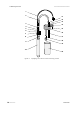
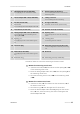
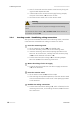
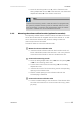
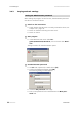
Table Of Contents
- Table of contents
- Table of figures
- 1 Introduction
- 2 Overview of the instrument
- 3 Installation
- 4 Operation
- 4.1 Fundamentals of operation
- 4.2 Instrument and Program Settings
- 4.3 Program information
- 4.4 Calibration functions
- 4.5 Methods
- 4.6 Determinations
- 4.6.1 Preparing samples
- 4.6.2 Preparing the instrument and the accessories
- 4.6.3 Preparing the determination
- 4.6.4 Starting the determination
- 4.6.5 Cleaning the instrument and accessories
- 4.6.6 Adjusting the method parameters during the determination
- 4.6.7 Stopping the determination manually
- 4.6.8 Status of the live curve
- 4.7 Results
- 4.8 GLP functions
- 5 Handling and maintenance
- 6 Troubleshooting
- 7 Technical specifications
- 8 Conformity and warranty
- 9 Accessories
- Index

■■■■■■■■■■■■■■■■■■■■■■
3 Installation
743 Rancimat
■■■■■■■■
15
1
FEP tubing 250 mm (6.1805.080)
For supplying air into the reaction vessel.
2
Silicone tubing (6.1816.010)
For connecting the reaction vessel to the
measuring vessel.
3
Thread adapter M8 / M6 (6.1808.090)
4
Tubing connector
For connecting the silicone tubing.
5
Air tube (6.2418.100)
6
O-ring (6.1454.040)
7
Connection
For connecting the thread adapter M8 / M6.
8
Reaction vessel cover (6.2753.107)
9
Foam barrier (6.1451.010)
10
Reaction vessel (6.1429.040)
11
Tubing adapter M8 / olive (6.1808.050)
For connecting the silicone tubing to the
opening In (5-13).
12
Opening "Out"
For removing the air from the measuring
vessel.
13
Opening "In"
For supplying the air to the measuring ves-
sel.
14
Labeling field
For entering the cell constant.
15
Connector plug
16
Measuring vessel cover (6.0913.130)
Contains integrated conductivity measuring
cell.
17
PTFE tube (6.1819.080)
For supplying the air to the measuring solu-
tion.
18
Electrode
19
Protection ring
20
Measuring vessel (6.1428.100)
Proceed as follows to mount the measuring and reaction vessel:
1
Mount the measuring vessel cover
■ Insert the PTFE tube (5-17) from above into the opening In (5-13)
of the measuring vessel cover.
■ Screw the tubing adapter M8 / olive (5-11) into the opening In of
the measuring vessel cover.
■ Place the measuring vessel cover (5-16) on the measuring vessel
(5-20).
2
Mount the reaction vessel cover
■ Insert the air tube (5-5) from below into the connection (5-7) of
the reaction vessel cover.
■ Place the O-ring (5-6) over the upper end of the air tube.
■ Screw the thread adapter M8 / M6 (5-3) gently into the connec-
tion (5-7) and, at the same time, press the air tube against the
thread adapter M8 / M6.