
User guide


4 Operation
732 IC Detector / 733 IC Separation Center
70
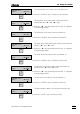
4.1.4 Flow chart for injection
The following flow diagram shows how an injection is started on the IC
system with and without a program. If the points <ZERO>, <FILL>
and "Siphoning in sample" are not programmed or must be performed
by the Autosampler, they must also be manually triggered. You will find
further information in the sections mentioned.
Program?Program?
yesyes
nono
EndEnd
StartStart
NewNew
program?program?
yesyes
nono
Editing programEditing program
sect. 4.7.1sect. 4.7.1
ProgramProgram
inactive?inactive?
yesyes
nono
Activating programActivating program
sect. 4.7.1sect. 4.7.1
CycleCycle
program?program?
yesyes
nono
<PROG R/S><PROG R/S>
sect. 4.7.2sect. 4.7.2
RemoteRemote
program?program?
yesyes
nono
Triggering remote startTriggering remote start
sect. 6.2sect. 6.2
InjectInject
program?program?
yesyes
<INJECT><INJECT>
sect. 4.6.2/4.7.1sect. 4.6.2/4.7.1
<ZERO><ZERO>
sect. 4.6.3sect. 4.6.3
<FILL><FILL>
sect. 4.6.1sect. 4.6.1
Siphoning in sampleSiphoning in sample
<INJECT><INJECT>
sect. 4.6.2sect. 4.6.2
Program executionProgram execution
(n cycles with "cycle")
nono