
User guide


4.1 Operating sequences
732 IC Detector / 733 IC Separation Center
69
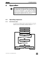
4.1.3 Flow chart for putting into operation
The following flow diagram shows how the IC system can be put back
into operation after a separating column has been removed and all de-
vices have been switched off (shutdown, see section 5.2.4). A require-
ment is that the installation (section 2.1) is complete and the basic set-
tings (section 4.1.2) have been made. You will find further information in
the sections mentioned.
Suppressor?Suppressor?
yesyes
nono
Preparing regeneration solutionPreparing regeneration solution
Preparing rinsing solutionPreparing rinsing solution
Switching on auxiliary pumpSwitching on auxiliary pump
sect. 2.8.6sect. 2.8.6
EndEnd
Preparing eluentPreparing eluent
sect. 5.1.3sect. 5.1.3
Preparing standards and samplesPreparing standards and samples
Switching on external devicesSwitching on external devices
Switching on 709 IC PumpSwitching on 709 IC Pump
Switching on 732 IC DetectorSwitching on 732 IC Detector
sect. 2.4.4sect. 2.4.4
Method?Method?
nono
yesyes
NewNew
method?method?
Setting parametersSetting parameters
sect. 4.5sect. 4.5
Developing a methodDeveloping a method
sect. 4.7.4sect. 4.7.4
Recalling methodRecalling method
sect. 4.7.4sect. 4.7.4
nono
yesyes
StartStart
Rinsing IC system with eluentRinsing IC system with eluent
StableStable
baseline?baseline?
nono
yesyes
Installing separating columnInstalling separating column
sect. 2.8sect. 2.8