
User guide


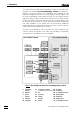
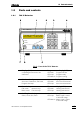

Table of contents
732 IC Detector / 733 IC Separation Center
V
List of figures
Fig. 1: Block diagram of the ion chromatography system ...........................................2
Fig. 2: Front of the 732 IC Detector ..............................................................................3
Fig. 3: Rear of the 732 IC Detector ............................................................................... 4
Fig. 4: Front of the 733 IC Separation Center............................................................... 5
Fig. 5: Rear of the 733 IC Separation Center................................................................ 6
Fig. 6: Connection 732 – 2.733.0010/2.733.0X30 ......................................................13
Fig. 7: Connection 732 – 2.733.0X20 .........................................................................15
Fig. 8: Setting the mains voltage ................................................................................18
Fig. 9: Connectors for capillaries................................................................................20
Fig. 10: Connection of 709 IC Pump ............................................................................ 21
Fig. 11: 6.2821.100 Filter unit PEEK .............................................................................22
Fig. 12: 6.2821.000 Filter unit Manufit...........................................................................23
Fig. 13: Connection to injection valve with PEEK capillaries........................................25
Fig. 14: Connection to injection valve with steel capillaries .........................................26
Fig. 15: Installing precolumn cartridges ....................................................................... 29
Fig. 16: Interior of the 733.0010 IC Separation Center ................................................. 34
Fig. 17: Interior of the 733.0X30 IC Separation Center.................................................36
Fig. 18: Connections at suppressor module................................................................38
Fig. 19: Ion chromatogram of the calibration ...............................................................61
Fig. 20: Ion chromatogram of the drinking water sample ............................................63
Fig. 21: Schematic representation of the instrument dialog......................................... 78
Fig. 22: Ion chromatogram for cation standard with Metrosep Cation 1-2 ................128
Fig. 23: Ion chromatogram for anion standard with Metrosep Anion Dual 2 .............131
Fig. 24: Assembling the suppressor...........................................................................142