
User guide
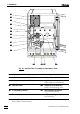


2.8 Separating columns and suppressor module
732 IC Detector / 733 IC Separation Center
39
• Attach inlet capillary 9090 using a 6.2744.010 Compression
fitting to the connector 5555 of the filter unit PEEK (see section
2.6.3).
• Attach a piece of the 6.1803.020 PTFE tubing (from 752
accessories) cut to the required length using a 6.2744.010
Compression fitting to the connector 5353 with filter at the other
end of the Filter unit PEEK.
• Attach the other end of the PTFE tubing using a 6.2744.010
Compression fitting to the 6.2744.030 Coupling (from 752 ac-
cessories) and mount it on the outlet end of the first length of
pump tubing.
• Mount a 6.2744.030 Coupling to the inlet end of the first
length of pump tubing. Attach a piece of the 6.1803.020 PTFE
tubing (aspirating tubing, from 752 accessories) cut to the
required length using a 6.2744.010 Compression fitting to the
other end of this coupling.
• Immerse the other end of the aspirating tubing in a vessel
containing regeneration solution (normally 20 mmol/L H
2
SO
4
)
and fix in place.
• Pull outlet capillary 9191 marked with "Waste" of the suppressor
module through the rear panel opening 4343, lead it to a suffi-
ciently large waste container and fix it in place.
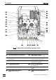
9 Suppressor connection 3: H
2
O
• Loosen rotary nipple screwed onto the interior side of con-
nection 2828. Pull inlet capillary 9393 marked with "H
2
O" (see
Fig. 17 and Fig. 18) by hand out of the opening of connection
2828 as far as required. Retighten nipple on the interior side of
connection 2828 to fix inlet capillary 9393.
• Attach inlet capillary 9393 using a 6.2744.010 Compression
fitting to the connector 5555 of the filter unit PEEK (see section
2.6.3).
• Attach a piece of the 6.1803.020 PTFE tubing (from 752
accessories) cut to the required length using a 6.2744.010
Compression fitting to the connector 5353 with filter at the other
end of the Filter unit PEEK.
• Attach the other end of the PTFE tubing using a 6.2744.010
Compression fitting to the 6.2744.030 Coupling (from 752 ac-
cessories) and mount it on the outlet end of the second
length of pump tubing.
• Mount a 6.2744.030 Coupling to the inlet end of the second
length of pump tubing. Attach a piece of the 6.1803.020 PTFE
tubing (aspirating tubing, from 752 accessories) cut to the
required length using a 6.2744.010 Compression fitting to the
other end of this coupling.
• Immerse the other end of the aspirating tubing in a vessel
containing rinsing solution (normally dist. H
2
O) and fix in
place.
• Pull outlet capillary 9292 marked with "Waste" of the suppressor
module through the rear panel opening 4343, lead it to a suffi-
ciently large waste container and fix it in place.