
User guide


2 Installation
732 IC Detector / 733 IC Separation Center
38
1
3
2
8989
9292
9393
94949090
9191
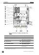
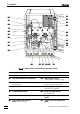
Fig. 18: Connections at suppressor module
• Screw outlet capillary 9494 to coupling 9696 using a 6.2744.010
Compression fitting.
• Screw inlet capillary 8282 of detector block 8181 to other end of
coupling 9696.
6 Fix connection suppressor – detector block
• Insert one of the column holders 8484 (6.2027.030, 6.2027.040
or 6.2027.050) in mounting rail 8383 and fasten coupling 9696 in
the column holder.
7 Prepare 752 Pump Unit
• Take two tubing cartridges out of the holder of the 752 Pump
Unit.
• Lay a length of 6.1826.050 Pump tubing in each of the two
tubing cartridges and reinsert these in the holder without
kinking the pump tubing.
• Regulate contact pressure on pump tubing in accordance
with the instructions printed on the pump.
Pump tubing is consumable material with a lifetime which depends on
the contact pressure. For this reason, raise the tubing cartridges
completely by loosening the clip on the right if the pump is switched
off for some considerable time (the set contact pressure remains
unchanged).
8 Suppressor connection 2: H
2
SO
4
• Loosen rotary nipple screwed onto the interior side of con-
nection 2727. Pull inlet capillary 9090 marked with "H
2
SO
4
" (see
Fig. 17 and Fig. 18) by hand out of the opening of connection
2727 as far as required. Retighten nipple on the interior side of
connection 2727 to fix inlet capillary 9090.
8989 Suppressor inlet
capillary for eluent
9090 Suppressor inlet
capillary for H
2
SO
4
9191 Suppressor outlet
capillary for H
2
SO
4
9292 Suppressor outlet
capillary for H
2
O
9393 Suppressor inlet
capillary for H
2
O
9494 Suppressor outlet
capillary for eluent
Eluent
H
2
O
Detector
Waste
Waste
H
2
SO
4