
User guide


2.8 Separating columns and suppressor module
732 IC Detector / 733 IC Separation Center
35
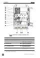
2.8.4 One-channel system without suppressor module
With the one-channel system without suppressor module, the IC sepa-
rating column is installed in the 2.733.0010 IC Separation Center as
follows (see Fig. 16):
1 Connect column to injector
• Remove end caps from column 7676.
• without precolumn:
Screw inlet end of separating column 7676 (note flow direction)
to column connection capillary 6767 mounted on the injector.
• with precolumn in twin cartridge holder:
Screw inlet end of separating column 7676 (note flow direction)
to outlet capillary 7272 (see Fig. 15).
• with precolumn in cartridge head:
Install separating column 7676 (note flow direction) in the car-
tridge head (see Fig. 15) as described in section 2.7.3.
2 Rinse column
• Place a beaker beneath the column outlet.
• Switch on 709 IC Pump and rinse the column for ca. 10 min
with eluent.
• Switch off IC Pump.
3 Connect column to detector block
• Screw outlet end of separating column 7676 to the inlet capillary
8282 permanently mounted on the detector block.
4 Fix column
• Insert one or two column holders 8484 (6.2027.030, 6.2027.040
or 6.2027.050) in the mounting rails 8383 and fasten separating
column in the column holder.
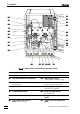
2.8.5 Two-channel system without suppressor module
With the two-channel system without suppressor module (2.733.0X20
IC Separation Center), the first IC separating column is connected on
the left side to injection valve A and detector block A as with the one-
channel system (see section 2.8.4 and Fig. 16). The second column is
connected on the right side to injection valve B and detector block B in
an analogous manner.