
User guide


7 Appendix
732 IC Detector / 733 IC Separation Center
212
IC precolumn cartridge PRP-1...........199
IC precolumn cartridge PRP-X100 .... 198
IC precolumn cartridge PRP-X300 .... 198
IC Pump 709
Automatic shutoff........................... 101
Connection at 732 ........................... 21
Electrical connection .......................21
Maintenance..................................134
Ordering designation.....................202
Practical notes............................... 134
RS232 settings ................................94
Settings................................... 101,131
Start/stop pump drive............. 106,112
Status messages.............................82
Switch on remote control................. 48
IC Sample Processor 766
Connection ...................................... 41
Ordering designation.....................202
IC separating column 7676
Changing.......................................138
Figure ....................................29,34,36
Install cartridge head.......................30
Installation................................... 35,37
IC separating columns
...................... see Separating columns
IC Separation Center 733
Certificate of Conformity
and System Validation...................208
Configuration................................... 95
Connection of 732 ........................... 13
Connection of 750 ........................... 41
Connection of 766 ........................... 41
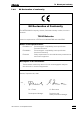
EU Declaration of conformity......... 206
External power supply ................... 187
Front ..................................................5
Interior.........................................34,36
Key field...........................................72
Opening...........................................10
Operating keys ................................76
Optional accessories..................... 196
Parts and controls .............................5
Rear ...................................................6
Settings............................................ 95
Standard equipment......................194
Technical data...............................192
Valve interfaces .............................188
id.1..................................................... 89
id.2..................................................... 90
Identical separation system...............138
Identification ................................. 89,122
Immunity to interference.................... 191
in position ....................................... 96
Increase in the baseline.....................140
Individual measured values...............120
Information on the
Instructions for Use............................8
Initial condition..................................... 48
Initialize data memory........................ 157
<INJECT> ................................... 76,104
inject..............................83,96,108,112
INJECT A............................................. 85
INJECT B............................................. 85
Inject program ...................................108
Injection ........................................96,104
Injection valve 6868
Connection of 709 ...................... 24,26
Figure ...............................25,26,34,36
Operation.........................................76
Settings....................................... 95,96
Switching .........................103,104,111
Inlet capillary 5656
Figure .........................................23,26
Installation ....................................... 23
Inlet capillary 7575
Figure .............................................. 29
Installation ....................................... 28
Inlet capillary 8282
Figure ......................................... 34,36
Installation ....................................... 35
Passivation ............................... 27,138
Inlet capillary 8787
Figure ......................................... 34,36
Inquiries.......................................... 54,77
Installation ...................................... 11,46
Installing precolumn cartridges........... 29
Installing the Manufit filter unit............. 23
Installing the PEEK Filter unit............... 22
Instructions for Use
(8.732.1033)............................... 8,193
Instrument adjustment....................... 176
Instrument description........................... 1
Instrument dialog............................ 54,77
Instrument information....................... 170
Instrument number ............................ 173
Instrument settings.............................. 91
Integrator start................................... 188
Interfaces........................................... 161
Interior of the 2.733.0010
IC Separation Center....................... 34
Interior of the 2.733.0X30
IC Separation Center....................... 36
Internal hardware test........................ 155
Introduction ........................................... 1
Ion chromatogram
of the calibration.............................. 61
Ion chromatogram of the
drinking water sample..................... 63
Ion chromatography.......................... 133
Ion chromatography system ................. 2
K
Key 2323 "FILL"
Figure ................................................ 5
Function......................................... 103
Key 2424 "INJECT"
Figure ................................................ 5
Function......................................... 104
Key 2525 "FILL"
Figure ................................................ 5
Function......................................... 103
Key 2626 "INJECT"
Figure ................................................ 5
Function......................................... 104
Key code .................................... 152,172
Key field............................................... 72
Key name ............................................ 71
Key table ........................................... 152
Keypad....................................... 190,192
Keypad test ....................................... 151
Keys
<ç> ....................................... 80,102
<è> ....................................... 80,102
<CLEAR>.................................. 76,80
<CONFIG> ............................... 74,88
<ENTER>............................. 76,79,80
<EVENT>................................ 74,114
<FILL> .................................... 76,103
<FULL SCALE> ...................... 73,102
<INJECT>............................... 76,104
<MARK>................................. 75,106
<METHOD>............................ 74,117
<PARAM>................................. 73,97
<PLOT>.................................. 75,122
<PRINT>................................. 75,119
<PROG R/S>.......................... 73,114
<PROGRAM> ......................... 74,107
<PUMP R/S> .......................... 74,106
<QUIT>................................ 76,79,80
<REPORT>............................. 75,124
<SELECT>................................ 76,79
<ZERO OFF> ......................... 74,106
<ZERO> ................................. 73,105
Knurled screw 3434
Figure................................................ 7
Open rear panel .............................. 14
Openin rear panel ........................... 13
Knurled screw 3737
Figure................................................ 7
Open rear panel ......................... 24,26
L
Labeling of the time axis ................... 100
Labeling of the x axis......................... 122
Labeling of the y axis ........................ 122
Leak testing......................................... 40
Leaks..................................... 10,101,148
left .................................................. 100
Left boundary.................................... 100
Linearity........................................ 98,189
Location .............................................. 12
Lock functions................................... 172
Loop program ....................... 91,107,110
Loss of suppressor capacity............. 143
M
Magnetic plate (6.2248.000)
Installation ....................................... 12
Ordering designation .................... 193
Main function keys 22
Figure................................................ 3
Overview..................................... 72,73
Main menu ..................................... 54,77
Mains cable
Connection...................................... 18
Ordering designation .................... 193
Mains connection
Procedure................................... 17,18
Safety notes..................................... 10
Technical data............................... 190
Mains connection plug 1818
Connection of mains cable ............. 18
Figure........................................... 4,18
Mains frequency................................ 190
Mains switch 99
Figure........................................... 4,18
On/off switching of
the instruments................................ 18
Mains voltage
Setting ............................................. 17
Technical data............................... 190
Maintenance............................... 133,136
Malfunctions............................... 145,148
Manufit filter unit.....see Filter unit Manufit
Manufit housing 6262