
User guide


7 Appendix
732 IC Detector / 733 IC Separation Center
210
config...............................................124
CONFIG/733 IC Sep.Cent.................. 95
CONFIG/733/suppressor....................96
CONFIG/733/valve A.......................... 95
CONFIG/733/valve B.......................... 96
CONFIG/aux/beep ............................... 92
CONFIG/aux/event .............................92
CONFIG/auxiliaries.......................... 91
CONFIG/detector ............................... 88
CONFIG/print meas.value................ 90
CONFIG/printer ................................. 89
CONFIG/RS settings.......................... 93
CONFIG/RS settings 709.................. 94
Configuration...................... 50,74,88,166
Configuration report ..........................124
Confirm of deletion .....................113,116
Confirmation........................................ 79
Confirmation of deletion ....................118
Confirmation of overwriting................118
Confirmation of parameters................. 76
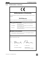
Conformity.........................................205
connected...........................................94
Connection 1313
Connection of detector block ..... 13,14
Figure ................................................4
Connection 1414
Connection of 733 ...................... 14,15
Figure ................................................4
Connection 1515
Connection of 709 ........................... 21
Figure ................................................4
Connection 2121
Connection of syringe...................... 16
Figure ................................................5
Connection 2222
Adjust aspirating tubing...................16
Figure ................................................5
Connection 2323
Attachment of
connection capillary 2222 ...................24
Connection of filter unit
Manufit 5858 .......................................25
Connection 2727
Connection of syringe...................... 16
Figure ................................................5
Installation of suppressor
inlet capillary....................................38
Connection 2828
Adjust aspirating tubing...................16
Figure ................................................5
Installation of suppressor
inlet capillary....................................39
Connection 3636
Connection of 732 ...................... 14,15
Figure ................................................7
Connection 4242
Connection of drain tube................. 16
Figure ................................................7
Connection 4545
Connection of 732 ........................... 15
Figure ................................................7
Connection 4848
Figure ................................................7
Pin assignment.............................. 187
Connection capillary 2222
Figure ..............................................25
Installation........................................ 24
Connection of
«IC Metrodata for Win95».................41
Connection of 709 IC Pump ................ 21
Connection of
733 IC Separation Center............... 13
Connection of 750 Autosampler.......... 41
Connection of
766 IC Sample Processor ............... 41
Connection of 791 VA Detector........... 41
Connection of a PC ............................. 44
Connection of a printer........................ 42
Connection of a recorder .................... 41
Connection of devices to the remote
interface........................................... 44
Connection of external devices ........... 41
Connection of syringe and aspirating
tubing .............................................. 16
Connection of waste container....... 14,15
Connection piece 9898
Cleaning ................................. 142,144
Figure ..................................... 142,143
Ordering designation..................... 201
Replacement ................................. 143
Connection to injection valve ......... 24,25
Connection to RS interface.................. 94
Connections ...................................... 136
Connections at
suppressor module ......................... 38
Connector 5353
Connection of
inlet capillary 9090 ......................... 38,39
Figure .............................................. 22
Installation ....................................... 22
Ordering designation..................... 198
Connector 5555
Connection of inlet capillary 9090 .. 38,39
Figure .............................................. 22
Installation ....................................... 22
Connectors for capillaries ................... 19
Contaminated valves......................... 134
Contamination with heavy metals...... 140
Contamination with organic
cationic complexing agents .......... 140
Contamination with
organic substances....................... 140
control............................................... 95
Control characters............................. 177
Control via RS232 interface................. 93
Correction............................................ 79
Correction factor........................... 57,102
Counterpart end 5858
Figure .............................................. 23
Installation ....................................... 23
Coupling 7070
Figure .............................................. 26
Installation ....................................... 25
Coupling 9696
Figure .............................................. 37
Installation ....................................... 38
Coupling (6.2620.040)....................... 196
Coupling (6.2620.060).... 27,137,138,194
Coupling (6.2744.020)....................... 195
Coupling (6.2744.030)....................... 197
Coupling (6.2744.040)....................... 195
Criterion for measured value printout.. 90
Current information............................ 170
Current time......................................... 81
cycle............................................ 83,107
Cycle program....................... 91,107,110
D
daily................................................. 115
Damping ................................. 56,99,189
damping............................................... 99
data bit........................................ 93,94
Data entry............................................ 79
Data output ....................................... 119
Data receipt......................................... 93
Data selection ..................................... 79
Data transmission protocol............... 177
Data transmission rate ........................ 93
Date....... 49,52,82,90,91,92,115,119,122
date ............................................. 92,115
date&time...................................... 90,91
Dead volume..................................... 148
Declaration of conformity.................. 205
DEFAULT............................................... 82
Default value ....................................... 77
Degassing of eluents ........................ 135
Degree of protection ........................... 10
Delete all events................................ 116
Delete all program steps................... 113
delete all?.............................. 113,116
Delete event ...................................... 116
Delete method................................... 118
Delete parameter values ..................... 76
Delete program steps ................ 109,110
delete?............................................. 118
Deleting characters............................. 80
Detector block 8181
Connection at 732........................... 13
Connection of
suppressor module......................... 35
Figure......................................... 34,36
Ordering designation .................... 193
Detector block (1.732.0100)......... 13,193
Detector block (1.732.0110)......... 13,193
Determination of
anions in drinking water .................. 45
Device label......................................... 92
device label..................................... 92
Device name ......................... 90,119,122
Diagnostic steps ............................... 149
Diagnostic tests ......................... 149,175
dialog................................................. 92
Dialog language............................. 53,92
Dialysis Unit 754
Connection at IC system................... 2
Ordering designation .................... 202
Dimensions ................................ 191,192
disabled........................................... 108
Display 11
Description...................................... 71
Error messages............................. 145
Figure................................................ 3
Representation.................................. 9
Standby mode................................. 81
Test................................................ 152
Display of date and time ..................... 82
Display of the absolute conductivity ... 82
Display of the auto-zero value............. 89
Display of the full-scale range............. 82
Display of the suppressor position...... 96
Display of the valve setting ............ 95,96
Displays in the standby mode............. 81