
User guide


2 Installation
732 IC Detector / 733 IC Separation Center
14
3 Connect waste container
• Lead the outlet capillary of the detector block to a sufficiently
large waste container and fix in place.
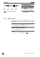
4 Connect 732 to 733
• Plug one end of the 6.2125.090 Connecting cable into con-
nection 1414 "733 IC Separation Center” of the 732 IC Detector
and fasten to the instrument by tightening the screws in the
cable connector (see Fig. 6).
• Plug the other end of the 6.2125.090 Connecting cable into
connection 3636 "732 IC Detector" of the 733 IC Separation
Center and fasten to the instrument by tightening the screws
in the cable connector (see Fig. 6).
2.3.2 2.733.0X20 IC Separation Center
For operation of the 2.733.0020 or the metal-free 2.733.0120 instrument
version of the 733 Separation Center, two 1.732.0100 or metal-free
1.732.0110 IC Detectors are needed. It is best to proceed as follows
when connecting the instruments and the two detector blocks:
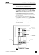
1 Install detector blocks
• Unscrew the four knurled screws 3434 from the top rear panel
3535 of the 733 IC Separation Center and remove rear panel
(see Fig. 5).
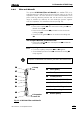
• Position first detector block A from the back in the space
provided in the 733 IC Separation Center on the right and
push fully to the front (see Fig. 16).
• Position second detector block B from the back in the space
provided in the 733 IC Separation Center on the left and push
fully to the front (see Fig. 16).
• Insert the cable permanently attached to detector block A in
opening 3333 and the outlet capillary in opening 32 32 "Waste A"
of the rear panel 3535.
• Insert the cable permanently attached to detector block B in
opening 2929 and the outlet capillary in opening 3030 "Waste B"
of the rear panel 3535.
• Replace rear panel 3535 and fasten to 733 IC Separation Center
with the four knurled screws 3434.
2 Connect detector blocks
• Plug the gray connecting cable permanently attached to
detector block A into connection 1313 "Detector block" of the
first 732 IC Detector and fasten to the instrument by tighten-
ing the screws in the cable connector (see Fig. 7).
• Plug the gray connecting cable permanently attached to
detector block B into connection 1313 "Detector Block" of the
second 732 IC Detector Block and fasten to the instrument by
tightening the screws in the cable connector.