
User guide


2.3 Connection of 733 IC Separation Center
732 IC Detector / 733 IC Separation Center
13
2.3 Connection of 733 IC Separation Center
2.3.1 2.733.0010/2.733.0X30 IC Separation Center
The instrument versions 2.733.0010 and 2.733.0030 of the IC Separa-
tion Center are operated with a 732 IC Detector whose standard
equipment also includes the 1.732.0100 Detector block. For the
metal-free 2.733.0130 instrument version the metal-free 1.732.0110
Detector block must be used. It is best to proceed as follows when
connecting the two instruments and the detector block:
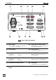
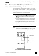
1 Install detector block
• Unscrew the four knurled screws 3434 from the top rear panel
3535 of the 733 IC Separation Center and remove rear panel
(see Fig. 5).
• Position detector block from the back in the space provided
in the 733 IC Separation Center on the right and push fully to
the front (see Fig. 16).
• Insert the cable permanently attached to the detector block in
opening 3333 and the outlet capillary in opening 3232 "Waste A" of
the rear panel 3535.
• Replace rear panel 3535 and screw to the 733 IC Separation
Center using the four knurled screws 3434.
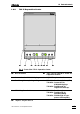
2 Connect detector block
• Plug the gray connecting cable permanently attached to the
detector block into connection 1313 "Detector Block" of the 732
IC Detector and fasten to the instrument by tightening the
screws in the cable connector (see Fig. 6).
RUN
COM
6.2125.090
Fig. 6: Connection 732 – 2.733.0010/2.733.0X30
Cable from
detector block