
User guide


2.1 Flow chart
732 IC Detector / 733 IC Separation Center
11
2 Installation
2.1 Flow chart
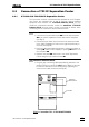
The following flow chart provides an overview of all installation work. You
will find more detailed information in the relevant sections.
733.0X20733.0X20
Setting upSetting up
Mains connectionMains connection sect. 2.4sect. 2.4
Connecting 709 IC PumpConnecting 709 IC Pump sect. 2.6sect. 2.6
PrecolumnPrecolumn
Precolumn with twin cartridge holderPrecolumn with twin cartridge holder sect. 2.7.2sect. 2.7.2
Precolumn with cartridge headPrecolumn with cartridge head sect. 2.7.3sect. 2.7.3
IC anion precolumn SUPERSEPIC anion precolumn SUPERSEP sect. 2.7.4sect. 2.7.4
733.0010733.0010 Connecting separating columnConnecting separating column sect. 2.8.4sect. 2.8.4
733.0X20733.0X20 Connecting separating columnConnecting separating column sect. 2.8.5sect. 2.8.5
733.0X30733.0X30 Connecting sep. col. + suppressorConnecting sep. col. + suppressor sect. 2.8.6sect. 2.8.6
Connecting 733Connecting 733 sect. 2.3.1sect. 2.3.1 Connecting 733Connecting 733 sect. 2.3.2sect. 2.3.2
Installing sample loopInstalling sample loop sect. 2.8.2sect. 2.8.2
ConditioningConditioning sect. 2.8.7sect. 2.8.7
Connecting external devicesConnecting external devices sect. 2.9sect. 2.9
Installing accessoriesInstalling accessories sect. 2.3.3/4sect. 2.3.3/4
YesYes
NoNo
YesYes
NoNo
YesYes
NoNo
YesYes
NoNo
YesYes
NoNo
metal freemetal free
NoNo
YesYes
PassivationPassivation sect. 2.6.7sect. 2.6.7
sect. 2.2sect. 2.2