
User guide


5 Notes – Maintenance – Faults
732 IC Detector / 733 IC Separation Center
152
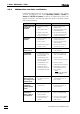
Key table
Code Key Code Key
0 <9 / METHOD> 12 <CLEAR>
1 <8 / PUMP R/S> 13 <SELECT>
2 <7 / CONFIG> 14 <3 / PRINT>
3 <ZERO> 15 <2 / REPORT>
4 <PARAM> 16 <1 / PLOT>
5 17
6 <6 / PROGRAM> 18 <ENTER>
7 <5 / EVENT> 19 <QUIT>
8 <4 / ZERO OFF> 20 <-/+ / è>
9 <PROG R/S> 21 <. / ç>
10 <FULL SCALE> 22 <0 / MARK>
11 23
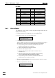
5.4.5 Check display
This diagnostic step is used to check all light emitting diodes and the
display for functionality.
• Prepare instrument for diagnostic test (see section 5.4.2).
• If need be, press <9> key repeatedly until
diagnosis
>diag/display test
• <ENTER>
After the <ENTER> key has been pressed, the program automatically runs through a
test sequence for a visual check on the light emitting diodes and the display.
⇒ The light emitting diodes for OVERLOAD, THERMOSTAT, ZERO and
PROG R/S are switched on for a certain time.
⇒ Power on test pattern (each pixel active) appears.
⇒ Both lines of the display are cleared.
⇒ Both lines of the display are written to with the characters “#”, “H”
and finally with “I”.
⇒ Both lines are written to from right to left with the continuous moving
display „0123456789ABCDEFGHIJKLMNOPQRSTUVWXYZ“.
⇒ The light emitting diodes for OVERLOAD, THERMOSTAT, ZERO and
PROG R/S flash in succession for a brief time.
• The test sequence can be held by pressing any key (with the excep-
tion of <9>) and restarted.
• The test is quit with the <9> key.
diagnosis
>diag/RS test