
User guide


4 Operation
732 IC Detector / 733 IC Separation Center
104
4.6.2 <INJECT> keys
The two <INJECT> keys at the 733 IC Separation Center have the
following function, depending on the instrument version:
733.0010 (1 valve) 733.0X20 (2 valves) 733.0X30 (valve+ suppr.)
INJECT
A
Switching of injection
valve A to "INJECT"
position
Switching of injection
valve A to "INJECT"
position
Switching of injection
valve A to "INJECT"
position
INJECT
B
No function Switching of injection
valve B to "INJECT"
position
No function
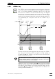
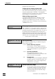
If the injection valve is in the
"INJECT" position, the green LED
in the key lights up. In this posi-
tion, the injection valve is con-
nected as shown in the diagram
opposite:
• The eluent flows via the sample
loop to the separating column.
This causes injection of the
sample previously added to
the sample loop.
• Sample inlet tubing and sy-
ringe are directly connected.
The "INJECT" function can be triggered at any time with the <INJECT>
key – also in the edit mode or when a program is running. If this is not
required, the key can be locked. For this, the parameter ">CONFIG/733
IC Sep.Cent./control" must be set to "732 only" under the
<CONFIG> key (see section 4.4.2). Switching of the injection valve is
then possible only using the 732 IC Detector via a programmed
"INJECT" command or with ">CONFIG/733 IC Sep.Cent./trigger = in-
ject". Switching of injection valve A to the "INJECT" position can also
be used for the automatic start of a program of the "inject" type.
With the 733.0X30 Separation Center, switching of the suppressor
module to the next position can be triggered automatically by the
switching of injection valve A to the "INJECT" position. For this, the pa-
rameter ">CONFIG/733/suppressor/auto step" must be set to
"inject" under the <CONFIG> key (see section 4.4.2).
12
4 5
3 6
Syringe
Column Eluent
Sample
Loop