
User Manual

13.113.1 DiagnosisDiagnosis
726 Titroprocessor, Instructions for use
266266
13.1.9 To check Analog Interface A
With this diagnostic step the analog inputs of Interface A can be checked for their function-
ality. For this test the testbox with article number 1.767.0010 is required.
1.
Prepare instrument for diagnostic test (see chap. 13.1.2).
2.
<Analog interf.>
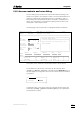
Ä On the screen there appears a window with the choice of selecting between analog interface A or B.
3.
With the cursor key, mark the letter A to select analog interface A.
4.
<ENTER>
5.
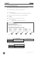
Connect Simulator to Titroprocessor accord. to Fig. 2.
6.
<All inp measure>
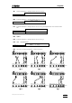
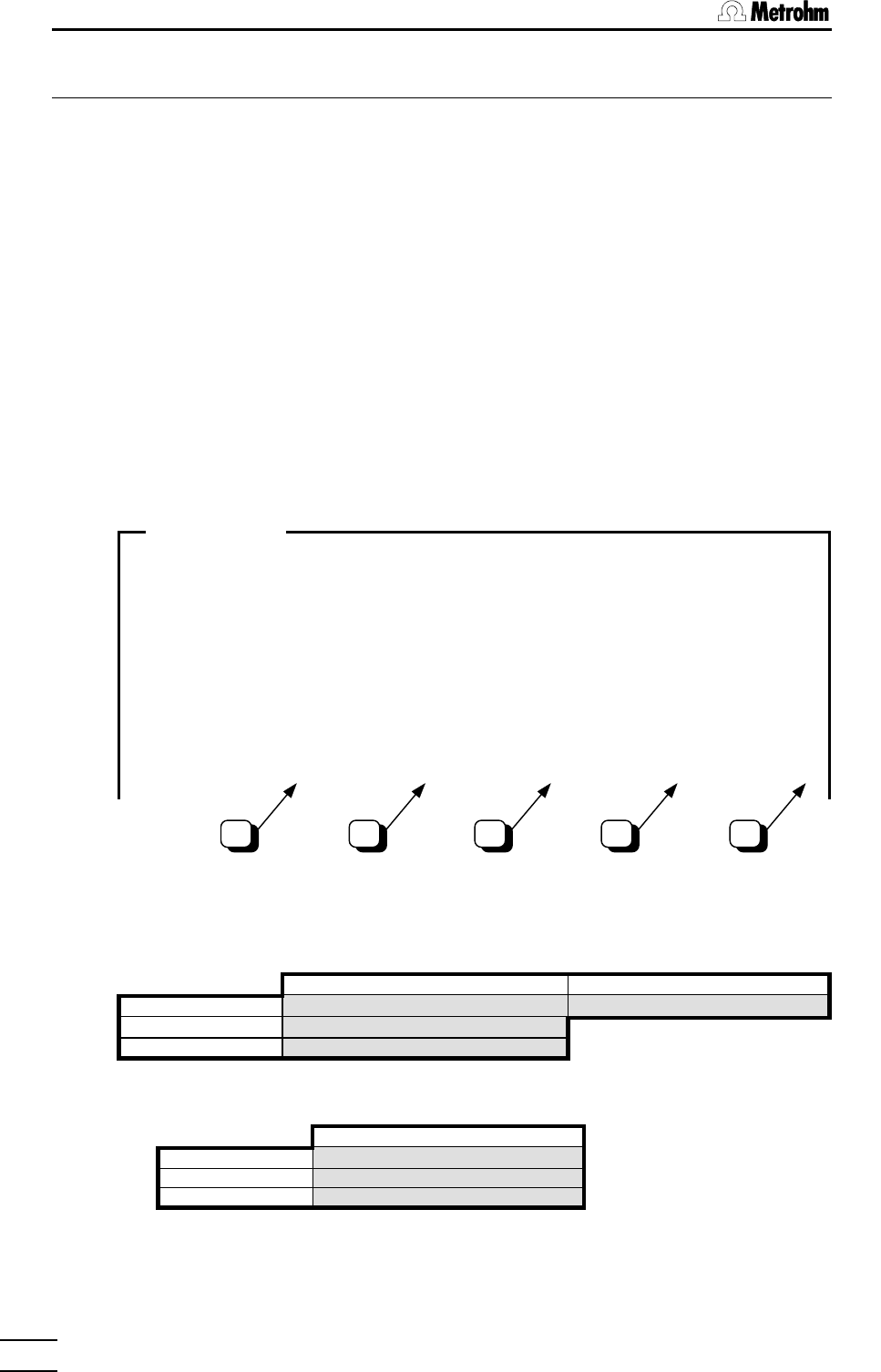
Ä The measurements are continuously updated and presented as follows::
Test date: ??-??-?? ??:??:??
Analog input measuring test
!!!!!!!!!!!!!!!!!!!!!!!!!!!!!!!!!!!!!!!!!!!!!!!!!!!!!!
Setting polarizing to: U=300 mV, I=10 uA
Display values as average of 6 meas. cycles
Analog interface A, Calib date: ??-??-?? ??:??:??
!!!!!!!!!!!!!!!!!!!!!!!!!!!!!!!!!!!!!!!!!!!!!!!!!!!!!!!!!!!!!!!!!!!!!!!!!!!!!!!!!!!!!!!!!!!!!!!!!!!!
Input 1 : ?x??????? ?.???? mV ?.???? mV/min ?.?? °C
Input 2 : ?x??????? ?.???? mV ?.???? mV/min ?.?? °C
Input Diff : ?x??????? ?.???? mV ?.???? mV/min ?.?? °C
Input Ipol : ?x??????? ?.???? mV ?.???? mV/min ?.?? °C
Input Upol : ?x??????? ?.???? mV ?.???? mV/min ?.?? °C
Fig. 1
7.
Check the following measuring values:
column C (see Fig. 1) column E (see Fig. 1)
Input 1 : +U / direct ± 0.4 mV Pt100 ± 0.3°C
Input 2 : +U / 1G ± 0.4 mV
Input Diff : 0 mV ± 4.0 mV
8.
Connect Simulator to Titroprocessor accord. to Fig. 3.
column C (see Fig. 1)
Input 1 : +U / 1G ± 0.4 mV
Input 2 : +U / direct ± 0.4 mV
Input Diff : 0 mV ± 4.0 mV
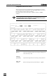
DIAGNOSIS WINDOW
A B C D E