711 Liquino Manual 8.711.
Metrohm AG CH-9101 Herisau Switzerland Phone +41 71 353 85 85 Fax +41 71 353 89 01 info@metrohm.com www.metrohm.com 711 Liquino Manual 8.711.1023 02.
Teachware Metrohm AG CH-9101 Herisau teachware@metrohm.com This documentation is protected by copyright. All rights reserved. Although all the information given in this documentation has been checked with great care, errors cannot be entirely excluded. Should you notice any mistakes please send us your comments using the address given above. Documentation in additional languages can be found on http://products.metrohm.com under Literature/Technical documentation.
Table of content page 1 Overview 1 1.1 Application range __________________________________________1 1.2 Application possibilities ____________________________________1 1.3 Instrument description______________________________________2 1.3.1 Front view ......................................................................................... 2 1.3.2 Rear view .......................................................................................... 3 2 Installation 4 2.
Table of content page 4.4 XDOS mode - controlled dosing ____________________________ 74 4.4.1 XDOS mode parameters ................................................................ 77 4.4.2 Examples of reports - XDOS mode ................................................ 81 4.5 SEQ mode - complex processes ____________________________ 83 4.5.1 Commands..................................................................................... 84 4.5.2 SEQ mode parameters ............................................
1. Overview 1 Overview 1.1 Application range The Metrohm 711 Liquino is a very versatile laboratory instrument which can be used everywhere that liquid handling is to be simplified and automated. This is the case in both analytical laboratories and in synthesis laboratories. It is equally suitable for both the preparation of complicated formulations in filling plants and also for simple delivery and pumping tasks involving toxic or aggressive media.
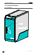
1.3 Instrument description 1.3 Instrument description 1.3.1 Front view Slot for memory card Always insert the card so that the upper edge of the card with the label faces right.
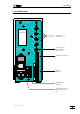
1. Overview 1.3.2 Rear view Made by Metrohm Herisau Switzerland Dos.1 Name plate Dos.2 Connections for 4 Dosinos Dos.3 Dos.
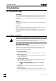
2.1 Instrument setup 2 Installation 2.1 Instrument setup Packaging The 711 Liquino is supplied in packaging which provides excellent protection. This includes a shock-absorbing plastic foam lining. Please store this packaging as it is the only way to guarantee damage-free transport of the instrument. Checks Please check immediately on receipt whether the shipment is complete and undamaged.
2. Installation 230 • Insert fuse holder Insert fuse holder and press it until it clicks into place. Fuse holder with window Mains switch Mains connection socket 2.2 Safety information General This instrument left our factory in perfect condition from a safety point of view. The following information must be carefully observed in order to maintain this condition and to ensure hazard-free operation.
2.2 Safety information cate the source of the fault with the aid of the diagnosis functions. If the cause of the malfunction cannot be found please contact the Metrohm service department. The instrument should only be opened when switched on under exceptional circumstances. As this exposes electrically live components it should only be carried out by an expert who is familiar with the risks involved. The instrument must be separated from all electricity sources before it is opened.
2. Installation 2.3 Setup 2.3.1 Connecting the keyboard The keyboard is connected to the keyboard socket provided for it on the rear panel of the instrument. 2.3.2 Connecting the Dosinos The Dosinos are connected to the sockets ”DOS1” to ”DOS4” on the rear panel of the 711 Liquino. Press each Dosino plug into the socket until it clicks into place! Dos.1 The notch on the plug must coincide with the marking on the panel.
2.4 Memory card 2.3.4 Installing the pipetting attachment The pipetting attachment available as an option is suitable for automatic pipetting functions with a Dosino 700. Connection to dosing port 1 of the Dosino 700 6.1562.050 Pipetting tubing Connection cable to 711 Liquino (remote connection) 6.1562.
2. Installation 2.5 Connections Metrohm automated systems with the 711 Liquino Seiko Citizen Epson HP IBM Printer Dosimats 665 .. 776 Balance other devices e. g. thermostat 691 692 712 713 Personal computer pH Meter / Conductometer 702 RS 232 Pt100 7 1 1 L iq u in o Titrino family Dos.1-4 ... 751 Remote 726 726 Titroprocessor 711 Liquino 683 Pump other devices 700 Dosinos 731 Relay box 730 730 Sample changer AC 772 Pump unit 711 Liquino, Instructions for use pumps heating bath etc.
2.5 Connections 2.5.1 Remote connections The remote control of instruments within a Metrohm automated system can (apart from data communication via RS232 interfaces) be carried out in a simple manner with the help of parallel-switched signal leads, the remote lines (or I/O lines). Signals can be set statically or transmitted as a signal pulse (usually approx. 200 ms duration); see SCAN and CONTROL commands, (page 91ff). The signal level is +5 volt (TTL-level) in each case.
2. Installation Connection cables Only Metrohm cables should be used to connect the 711 Liquino to other instruments as these are the only ones with which interference-free data transmission can be guaranteed. Note: Remote cables for the 711 Liquino always have a name on the end of the cable to indicate the instrument with which the particular plug is intended to be used and which connection it should be plugged in to.
2.5 Connections 711 Liquino — Titrino — 683 Pump — 730 Sample Changer 3 0 683 Pump Unit 2 I 0 A B Titrino 683 Pump Unit 730 C I 0 D cable 6.2141.100 Cable 6.2141.100 is used for the SMPL mode if aspiration and rinsing the titration vessel are to be carried out as quickly as possible (with 2 x Pump 683). The sample changer connection can be left open if no sample changer is required.
2.
2.5 Connections Example of a sample changer method: >st ar t sequence 1 CTL: Rm: ← Initialize remote interface I NI T >sampl e sequence 1 CTL: Rm: START devi ce1 2 SCN: Rm: r eady1 3 Li f t : 1: shi f t 4 CTL: Rm: * * * * * * * * * 1* * * * 5 Wai t 1 6 CTL: Rm: * * * * * * * * * 0* * * * 7 Move: 1: sampl e 8 Li f t : 1: wor k 9 CTL: Rm: * * * * * * * * * 1* * * * 10 Wai t 1 11 CTL: Rm: * * * * * * * * * 0* * * * 12 SCN: Rm: r eady1 13 Move: 1: spec.
2. Installation 731 Relay Box settings: Connect 772 Pump Unit to DC1 (or DC2) Output voltage: 18 or 24 volt Remote address selection disk DC1: 7 (=Output 7) Connect heating bath to AC1 (or AC2, mains voltage) Remote address selection disk AC1: 2 (=Output 2) 711 Liquino settings Temperature monitoring XDOS mode (contained in SEQ mode): Par amet er s >XDOS moni t or i ng t emper at ur e: l ow l i mi t upper l i mi t act i on: al ar m pi ns: on xx° C ... ...
2.5 Connections 2.5.2 Serial connections A wide range of possible connections can be made at the RS232 interface. As well as all Metrohm instruments which are equipped with the Metrohm remote control language, a printer (requirement: serial interface or parallel/serial converter) or a personal computer (PC) can also be connected. Any instrument from another manufacturer which is equipped with a serial RS232 interface can also be connected. 711 cable 6.2134.040 (9-pin/9-pin) or 6.2134.
2. Installation 2.5.3 Connecting a printer Printers with the following printer drivers can be connected: IBM Epson Seiko Citizen HP IBM Proprinter and printers with IBM emulation Epson printers and printers with Epson emulation Seiko printer DPU-411 or DPU-414 Citizen printer IDP560 RS HP printers and printers with HP PCL3 emulation If you wish to connect a different printer then ensure that this can emulate one of the printer modes supported by the 711 Liquino.
2.5 Connections Printer Seiko DPU-414 Cable 6.2125.130 RS232 settings baud rate: 9600 data bit: 8 stop bit: 1 parity: none handshake: Hardware send to: Seiko Settings on printer Recommended DIP switch settings: Dip SW-1 OFF ON ON OFF ON OFF ON ON 1 2 3 4 5 6 7 8 Dip SW-2 ON OFF ON ON ON ON OFF OFF Dip SW-3 ON ON ON ON OFF ON ON ON Depending on the set dialog language, the adjustable 7-bit ASCII character set of the printer will be set automatically to the national character set.
2. Installation 2.5.4 Connecting a balance The following balances can be connected to the RS232 output of the 711 Liquino: Balance Cable Sartorius MP8, MC1 6.2134.060 Mettler AB, AG (LC-RS25) supplied with balance Mettler AM, PM from Mettler: ME 33995: green wire to Pin 2, brown wire to Pin 3, white wire to Pin 7, yellow wire to Pin 20 of the 25-pin plug + 6.2125.
3.1 The Liquino concept 3 Introduction 3.1 The Liquino concept The 711 Liquino is designed so that, together with one or more 700 Dosinos, it can automate a wide range of tasks in the laboratory. Everything which falls under the general heading of 'liquid handling', i.e. the transport of liquids in any form, belongs to its range of applications. Its functions can be divided up into three steps. • Simple manual dosing and dispensing with up to four dosing devices.
3 Introduction 3.2 Tutorial This tutorial will introduce you step by step to the operation of the Metrohm 711 Liquino. It is arranged so that you can work through it from the beginning to the end and in this way become familiar with the most important functions of the instrument. You will be guided through each section step by step so that you will be able to carry out the simplest settings. You can also carry out further fine adjustments. The necessary information for this can be found in section 4. 3.2.
3.2 Tutorial 3.2.2 Defining dosing units In order for the complete tubing system of a Dosino to be fully filled with the reagent solution without any air bubbles the 711 Liquino must know the dimensions of the connected tubing. For this reason a dosing unit can be defined in the configuration menu and then selected for the method. *) Except for the "Sampling dosing unit" in the SMPL mode the standard port occupancy for all modes is as follows: Port 1: Port 2 (bottle): A • Press and then 3x <>.
3 Introduction di am. t ube2 2. 0 mm • The inner diameter of the tubing at Dosino port 2 can be entered here and confirmed with . Di spl ay: >dosi ng uni t s l engt h t ube3 1 0 mm • As no tubing is connected to Dosino ports 3 and 4 the tubing lengths must be set to 0 mm. Check this for port 3, press and check the value for port 4 (the diameter is not requested if the length has been set to 0 mm). Press again.
3.2 Tutorial 3.2.3 Dosing and dispensing This is where you learn the simplest functions of the Liquino: manual dosing and dispensing. Fit a reagent bottle with a dosing unit and a Dosino and connect the Dosino to the Liquino. Select, e.g. connection socket 'Dos. 1' or 'Dos. 2' for this. Now switch the 711 Liquino briefly off and then on again. In this way the instrument recognizes the connected Dosino. Details about setting up dosing units can be found in section 6.1.2, page 143.
3 Introduction J A CONFIG • If you do not want the dosing speed to increase or you require a quicker increase in the dosing speed then you can set this in the configuration. • Press the key and the <> key twice. 2x Di spl ay: conf i gur at i on >manual • Here you will find the submenu with the settings which are effective for manual functions.
3.2 Tutorial MAN OFF D • MANUAL Operating the key switches manual operation off again. The Liquino is again in the basic condition. If you want to dose a particular volume several times then select the 'Dispense' function. Proceed in a similar manner to dosing. MAN OFF D • MANUAL Switch the Liquino to the manual operating mode by pressing the key. Di spl ay: DOS NR P • manual r eady 0. 000 mL Use the key to select the connected dosing device.
3 Introduction J A CONFIG • If you want, you can configure your Liquino so that after each dispensing process the dosing cylinder is refilled automatically. • Press the key and the <> key twice. 2x Di spl ay: conf i gur at i on >manual • Here you will find the submenu with the settings which are effective for manual functions. Di spl ay: >manual dos.
3.2 Tutorial 3.2.4 Changing the dosing unit A dosing device consists of a dosing unit (the green part) with a dosing cylinder (2, 5, 10, 20 or 50 mL) and the dosing drive, the Dosino 700. If you are working with different reagents then you do not need a separate dosing drive for each reagent bottle. Fit the individual reagent bottles with a dosing unit (the actual buret) and simply mount the dosing drive connected to the Liquino or dosing unit on a different reagent bottle as it is required.
3 Introduction 3.2.5 Temperature measurement The 711 Liquino is equipped with a Pt100 temperature measuring input. Apart from temperature-controlled dosing this means that simple manual temperature measurements can also be carried out. MAN OFF D TEMP MANUAL 9 I • Connect a Pt100 temperature sensor. The connection socket is on the rear panel of the 711 Liquino. Use the key to switch to manual operation. Then press . Di spl ay: • MAN OFF D manual 21.
3.2 Tutorial 3.2.6 PIP – precise pipetting/diluting Example: Pipet 1mL and dilute with 9mL. Distilled water is used as the "hydraulic“ liquid. Preconditions / Preparation The easiest and most accurate means of pipetting is with pipetting attachment 6.1562.040. The keyboard can be used to proceed from step to step. Define a dosing unit which corresponds to the tubing of the Dosino used. This procedure is described on page 22.
3 Introduction dr i ve uni t :
3.2 Tutorial Z START • From now on when is pressed the method will be run immediately. *) • The pipetting process consists of several steps. For each step instructions are shown on the display. If the pipetting attachment is used then the key built into the handle can be used to switch from one step to the next. The pipetting process can also be started with it. Whenever the LED on the handle lights up the 711 Liquino is ready for the next step.
3 Introduction 3.2.7 SMPL – fully automatic sampling The capabilities and possible uses of an SMPL method will be demonstrated by means of a complexometric titration of Ni2+ with the help of the 711 Liquino and Titrino 716. Chemistry The Ni2+ ion is buffered to pH 10, complexed with Cu-EDTA and then titrated with Na-EDTA.
3.2 Tutorial A new titration can now be carried out. The number of determinations and the number of times the cell is to be rinsed out can be entered. The Liquino offers the possibility of carrying out titrations comfortably and confidently. Even if the titration cell is only rinsed out once the variations only amount to 0.01 to 0.02%. Multiple determinations at defined time intervals are also possible (e.g. periodic sampling of a sample flow).
3 Introduction The dosing units which correspond to the tubing used for the Dosinos must be defined. This process is described on page 16. Method editing MODE * - X DOS NR P SELECT • The SMPL mode must first be activated. This sets all method parameters to standard values. Press the key and then
3.2 Tutorial di l ut i on vol . • The dilution volume is the amount of solvent to be added to the measuring cell after the sample has been transferred there (in the example 3 mL). Press to accept the value. Di spl ay: >SMPL sampl i ng oper at i on sampl e r i nse r ep. 1 • Enter how often the cylinder is to be rinsed with the sample. If samples are being transferred which do not greatly differ from one another 1 rinse is sufficient. Press to accept the value.
3 Introduction Di spl ay: >SMPL meas. cel l r i nsi ng r i nsi ng vol ume 30. 0 mL • The amount of solvent to be used to rinse the measuring cell is entered here. In this example 30 mL are sufficient. Press to accept the value. Di spl ay: >SMPL meas. cel l r i nsi ng r i ns. r at e max mL/ mi n • The measuring cell should be rinsed as rapidly as possible, so that the rate can be left at ‘max’. Press . Di spl ay: • As the ‘SMPL meas.
3.2 Tutorial the value with . Di spl ay: • The rate of addition for the pH 10 buffer can be entered here. The maximum rate (default) is already correct. Press . Di spl ay: >>aux. sol ut . AFTER no1 f eed r at e max mL/ mi n >>aux. sol ut . AFTER no1 f i l l r at e max mL/ mi n • This is the rate at which the Dosino cylinder will be refilled. The default value (max) can be accepted with . Di spl ay: >>aux. sol ut .
3 Introduction Di spl ay: par amet er s >SMPL pr esel ect i ons • As the ‘SMPL control I/O’ submenu contains no further menu items, an automatic return is made to the submenu selection. The parameter menu is exited with . The instrument is now ready to carry out the SMPL method. Various SMPL methods can be edited and then stored in the method memory. Each of these methods can then be reloaded by pressing a few keys. The method memory is described on page 128.
3.2 Tutorial 3.2.8 CONT – the automatic volumetric flask A typical daily task is the preparation of standard solutions. Preparing serial dilutions is often time-consuming and involves making calculations. The CONT/volume fraction mode of the 711 Liquino allows this monotonous routine work to be automated. Example: the preparation of a standard for the determination of chloride in drinking water by ion chromatography. The sample to be determined has chloride content of about 10 ppm.
3 Introduction • Accept the entry with . Di spl ay: >CONT par amet er s meas. uni t : mol / L • Use the
3.2 Tutorial A CONT method can be edited and stored in the method memory for each standard solution. Each of these methods can then be reloaded by pressing a few keys. The method memory is described on page 128.
3 Introduction 3.2.9 XDOS – the electronic dropping funnel 120mL of solution are to be added in 5 hours. This can be carried out easily and reliably with a tandem addition using 2 Dosinos. In this way interruptionfree addition is guaranteed. Preconditions / Preparation The accessories for tandem addition (see ”ordering information” in the ”711 Liquino” leaflet) are required for the tubing. However, it is also possible to lead a separate tubing from each Dosino to the test apparatus.
3.2 Tutorial >XDOS par amet er s J • <> is used to open the next submenu. Di spl ay: par amet er s >XDOS dosi ng uni t s • Press to access the submenu ‘XDOS dosing units'. Di spl ay: >XDOS dosi ng uni t s set up: si ngl e • Use the
3 Introduction Various XDOS methods can be edited and stored in the method memory. Each of these methods can then be reloaded by pressing a few keys. The method memory is described on page 128. Running the method Z START • When is now pressed the display shows Di spl ay: Not pr epar ed yet ! Run PREP now? • Before the Dosino is used for the first time in the new configuration the Dosino cylinder and the complete tubing system must be filled bubblefree with the reagent solution. Press .
3.2 Tutorial 3.2.10 XDOS – temperature-controlled addition Example: during the preparation for a nitration 0.3 mol semi-concentrated hydrochloric acid is to be added to 0.1 mol freshly distilled aniline. During this process the temperature of the mixture should, if possible, not exceed 10°C. The 711 Liquino will carry out the reagent addition and control the temperature.
3 Introduction B PARAM • The key is used to access the parameter menu, where all the possible settings for an XDOS method can be found. Di spl ay: • The submenu ‘XDOS parameters’ contains the main settings for an XDOS method. Press to open the submenu. Di spl ay: >XDOS par amet er s t emp. measur i ng: of f • The colon indicates that the
3.2 Tutorial dos. uni t : st andar d
3 Introduction
3.2 Tutorial Running the method Z START • When is now pressed the display shows Di spl ay: Not pr epar ed yet ! Run PREP now? • Before the Dosino is used for the first time in the new configuration the Dosino cylinder and the complete tubing system must be filled bubblefree with the reagent solution. Press . YES ENTER Di spl ay: Put t i p i n vessel ! Run PREP? • Take care that the tip of the dosing tubing is located in a vessel and then press .
3 Introduction 3.2.11 SEQ – complex procedures under control Example: the preparation of phenolazonaphthol. A short version of the synthesis procedure might read as follows: " 0.3 mol of a semi-concentrated hydrochloric acid is added to 0.1 mol freshly distilled aniline. The temperature should remain below approx. 10°C. After cooling the mixture to 0°C a 0.1 mol solution of NaNO 2 is added so that temperature does not exceed 5°C. When this addition is complete 8% β-naphthol solution (2 molar) is added.
3.2 Tutorial For the other two XDOS methods (diazotization and azo coupling) the parameter lists are printed out below. Use these lists together with the practical experience already gained to enter the parameters. Lines marked with ( adapt ) must be adapted to the existing conditions. XDOS method for diazotization 711 Li qui no dat e 1998- 07- 08 t i me 18: 16 mode: XDOS user met hod: par amet er s >XDOS par amet er XDOS t ype: vol ume&r at e vol ume 80. 0 f eed r at e 30. 0 t emp. measur i ng on r ec.
3 Introduction XDOS method for azo coupling 711 Li qui no dat e 1998- 07- 08 t i me 18: 42 mode: XDOS user met hod: par amet er s >XDOS par amet er XDOS t ype: vol ume&r at e vol ume 400. 0 f eed r at e 30. 0 t emp. measur i ng on r ec. i nt er val 00: 01: 00 f i l l r at e max aut o f i l l on >XDOS dosi ng uni t s set up: si ngl e dosi ng dr i ve: DOS3 dos. uni t : AZO1 por t use: def aul t >XDOS moni t or i ng t emper at ur e: on l ow l i mi t - 70 upper l i mi t 10.
3.2 Tutorial SEQ method editing As the sub-methods have now been defined and stored, the SEQ method can now be assembled. MODE * - X DOS NR SELECT P • The SEQ mode must first be activated. This sets all method parameters to standard values. Press the key and then
3 Introduction command: NO OPERATI ON • "4. Pause for 1 minute.“
3.2 Tutorial Running the method Z START • When is now pressed the display shows Di spl ay: Not pr epar ed yet ! Run PREP now? • Before the Dosino is used for the first time in the new configuration the Dosino cylinder and the complete tubing system must be filled bubblefree with the particular reagent solution. Press .
3 Introduction 3.2.12 GLP – automatic validation For the automatic validation of a Dosino or the dosing unit a balance *) must be connected to the 711 Liquino via the RS interface (see also page 19). In the GLP mode the Liquino automatically adds liquid to a tared vessel on the analytical balance, calculates the volume of the liquid added and compares this with the theoretical volume. The validation protocol is printed out on the connected printer in agreement with GLP practice.
3.2 Tutorial Creating the GLP method MODE * - X DOS NR SELECT P • The GLP mode must first be activated. This sets all method parameters to standard values. Press the key and then
3 Introduction Di spl ay: >GLP opt i ons bal ance- I d • Enter an unambiguous identification for the balance used (e.g. serial number). The input of text is explained on 63. Di spl ay: par amet er s >GLP r epor t s • As the ‘GLP options’ submenu contains no further menu items, an automatic return is made to the submenu selection. Press to open the submenu ‘GLP reports’. The reports which are to be printed out automatically at the end of the GLP test are defined here.
3.2 Tutorial Running the GLP method Z START • When is now pressed the display shows Di spl ay: • Before a GLP test it is absolutely necessary that the Dosino cylinder and the complete tubing system must be filled bubble-free with reagent solution. Press . YES ENTER Di spl ay: <1> or <2> Z START 60 Not pr epar ed yet ! Run PREP no? wast e por t : t i p( 1) or f l ask( 2) ? • Press <1> to empty the contents of the cylinder through the dosing tip or <2> to return them to the bottle.
4. Detailed description 4 Detailed description 4.1 The keyboard Metrohm 711 Liquino Controller DOS1 Menu keys DOS2 A CONFIG B PARAM MAN OFF D C USER METHOD E MANUAL F HOME K J Editing and navigating ALPHA END O INSERT DOS NR SELECT U DELETE P Q CLEAR NO YES QUIT ENTER DOSING 7 PREP 4 G L CUR DATA R DISPENSE H 8 FILL 5 1 2 MEM CARD V PRINT 0 CONTINUE Y HOLD 6.2142.020 Dosing device LEDs DOS4 DOS3 M .
4.1 The keyboard 4.1.1 Menu keys A Opens the configuration menu. For details see page 69. B Opens the parameter menu. For details see page 74ff. CONFIG PARAM C USER METHOD Opens the method storage menu. For details see page 128. See also key. 4.1.2 Action keys CONTINUE Y Interrupts an automatic procedure or continues it again. HOLD Stops an automatic procedure. STOP Z Starts a method or a manual function. START 4.1.
4. Detailed description NO Exits a submenu or confirms an error message. QUIT Q CLEAR YES Completely deletes an entry during editing or deletes the last character in the text input mode. Confirms an entry during editing. Opens a submenu during navigating. ENTER MAN OFF D Switches on (or switches off) manual operation. MANUAL 4.1.4 Manual functions and other keys DOSING 7 G DISPENSE H 8 TEMP 9 PREP 4 FILL 5 EXCH 6 I M Manual filling of a dosing unit.
4.1 The keyboard PRINT . MODE *- W Prints out various reports. X Selects an automatic run mode: • XDOS - controlled dosing • PIP - pipetting • CONT - preparation of solutions • SMPL - automated sampling • SEQ - sequential procedures • GLP - validation mode for dosing units Selection is made either with the
4. Detailed description 4.2 Editing The instrument dialog system of the Liquino 711 is chiefly organized as a menu system. For example, the key forms the access to the configuration menu of the basic settings and the key provides access to the parameters of a run mode or a method. The menus are further split up into submenus. 4.2.1 Navigating in menus YES • ENTER Use the key to view and process the individual lines in a menu.
4.2 Editing 4.2.3 Text input The text editor can be used wherever a text input is required. Numbers can be entered directly. The key can be used to switch between four sets of characters. • • • • Capital letters (ALPHA character set) Lower case letters (alpha character set) Special character set 1 Special character set 2 The individual characters can then be entered directly via the keyboard. Observe the red printing on the keys.
4. Detailed description Example: >st or e met hod met hod: ******** First press the key to delete the current contents. Open the text editor with the key. ALPHA ALPHA met hod: The keyboard letters are now active. ‘ALPHA’ is in capital letters, i.e. all letters entered will appear as capital letters. Enter 'HC'. al pha met hod: HC Press the key again to allow lower case letters to be entered. (‘alpha’ is now in lower case letters). Type in 'l'.
4.3 Configuration 4.3 Configuration In order for the different modes and commands of the Liquino 711 to function properly it is essential that it is configured carefully. In particular, the definition of the different types of dosing unit and the serial RS 232 interface require special care. 4.3.1 Defining the dosing units Depending on your requirements you can fit your dosing units with tubing of different lengths and thicknesses. This results in different tubing volumes.
4. Detailed description 4.3.2 The configuration menu Please note: menu entries with a colon offer a selection list. Press the
4.3 Configuration >dosi ng uni t s Configuration of dosing units If dosing units with different lengths and diameters of tubing are used which do not correspond to the standard dimensions then special types of dosing units can be defined (max. 10). If such a dosing unit is used then its name must be entered under 'Configuration>Manual operation' or in the method with which it is to be used. dos. uni t : D1 selection list, see 'I D' below ID D1 12 ASCII characters as wished selects dosing unit.
4. Detailed description >>er r . l i mi t s 20mL- cyl . Submenu for 20 mL dosing units er r or max. vol . +/ - 60 µL 1…999 µL maximum volume error sl ope +/ - 0. 003 0.001…0.1 maximum variation in slope i nt er cept +/ - 30 µL 1…99 µL maximum y-axis intercept >>er r . l i mi t s 50mL- cyl . Submenu for 50 mL dosing units er r or max. vol . +/ - 150 µL 1…999 µL maximum volume error sl ope +/ - 0. 003 0.001…0.
4.3 Configuration >keyboar d opt i ons l ock conf i gur at i on: of f Locks key on = configuration menu is not available off >keyboar d opt i ons l ock par amet er s of f Locks key on = Parameters cannot be altered off >keyboar d opt i ons >>user met hods Submenu for locking the memory functions. Press . The settings in this submenu only affect the internal method memory. The memory card can still be used.
4.
4.4 XDOS mode - controlled dosing 4.4 XDOS mode - controlled dosing The XDOS mode (= Extended Dosing) of the 711 Liquino allows controlled dosing of liquids with variable parameters. In principle it is possible to select one of three different types of dosing. If continuos dosing is required a tandem dosing setup can be used, i.e. dosing is carried out with a combination of two Dosinos so that while one Dosino is being filled the other Dosino carries out the dosing and vice versa.
4. Detailed description The following equation can be used to estimate whether the max. dosing rate will be used: Dosi ng r at e = r equi r ed del i ver y r at e ( i n mL/ mi n) ∗ 2. 22 If the required dosing rate exceeds the max. dosing rate for the selected dosing unit (or cylinder volume) then a larger dosing unit must be selected. The limits of the individual dosing units: Cylinder vol. Max. dosing rate 2 mL 5 mL 10 mL 20 mL 50 mL 6.66 mL/min 16.66 mL/min 33.33 mL/min 66.66 mL/min 166.
4.4 XDOS mode - controlled dosing However, in order to ensure interruption-free dosing the following points must be taken into account: • In order to keep the filling times as short as possible use the highest filling rate permitted. Take the liquid viscosity and density into account. • The dosing rate must not exceed 85% of the filling rate value. At the max. filling rate this corresponds to the following values: Cylinder volume 2 mL 5 mL 10 mL 20 mL 50 mL Max. dosing rate 5.10 mL/min 12.75 mL/min 25.
4. Detailed description 4.4.1 XDOS mode parameters B PARAM Main menu: All settings in the parameter menu form a method and can be stored as such.
4.4 XDOS mode - controlled dosing Maximal values for dosing and filling rates Cylinder vol. max. rate 2 mL 6.66 mL/min 5 mL 16.66 mL/min 10 mL 33.33 mL/min 20 mL 66.66 mL/min 50 mL 166.66 mL/min These are pure piston stroke rates; filling times not taken into account. >XDOS par amet er f i l l r at e max mL/ mi n Filling rate of dosing unit max, = highest possible filling rate (depends on type of dosing 0.001…166.66 unit.
4. Detailed description par amet er s >XDOS moni t or i ng Monitoring function settings Navigate with >XDOS moni t or i ng t emper at ur e: of f Temperature monitoring on, off >XDOS moni t or i ng l ow l i mi t - 70 ° C Lower temperature limit -70…200.0 >XDOS moni t or i ng upper l i mi t 200 ° C Upper temperature limit -70…200.
4.
4. Detailed description 4.4.2 Examples of reports - XDOS mode Temperature-controlled dosing with volume and time selection Parameter Report 711 Liquino 0220 711.0011 date 1998-09-30 time 11:51 *** Dev. Dept. *** dm *** Metrohm Ltd mode: XDOS user method: TempDos1 lot no. 12-2 parameters >XDOS parameter XDOS type: volume&time volume 10.0 mL dosing time 00:02:00 temp. measuring: on rec. interval 00:00:10 fill rate max mL/min auto fill: on >XDOS dosing units setup: single dosing drive: DOS1 dos.
4.4 XDOS mode - controlled dosing Curve Report 711 Liquino date 1998-09-30 *** Dev. Dept. *** dm *** Metrohm Ltd mode: XDOS lot no. 0220 time 11:39 711.0011 user method: TempDos1 12-2 ← volume/temperature curve Temperature limit reached Temperature limit Temperature curve Volume curve Dosing interrupted ============ Combined List 711 Liquino date 1998-09-30 *** Dev. Dept. *** dm *** Metrohm Ltd mode: XDOS lot no. 0220 time 11:39 711.0011 user method: TempDos1 12-2 time vol.
4. Detailed description 4.5 SEQ mode - complex processes The SEQ mode (sequence) of the Liquino allows complex process sequences with a total of up to 75 steps to be created. The individual steps can consist of methods (stored modes) or auxiliary commands. Sequences can be processed several times in automatic operation.
4.5 SEQ mode - complex processes The process sequence is defined in the parameter menu and is part of the method. The individual steps can be programmed in sequence. It is possible to insert steps in the sequence at a later date ( key) or to delete whole steps from the sequence ( key).
4. Detailed description Auxiliary and communication commands Time-oriented auxiliary commands and communication commands are available. • PAUSE — this command interrupts sequence processing for a defined period. • TIMER — sequence processing is interrupted until a defined time (date and time) has been reached. • CONTROL — during the sequence processing it is possible to set a particular signal pattern at a remote connection or to send a character string via an RS232 connection to a connected instrument.
4.5 SEQ mode - complex processes RS232 connection: Data (=character strings) can be sent to connected instruments via the serial RS interface. Make sure that the transmission parameters of the RS232 interface agree with those of the connected instrument (see configuration menu >RS232 Settings, page 21). Any combination of letters, numbers and special characters can be selected from the Liquino character set. To enter letters and special characters press the key, see also page 66.
4. Detailed description Input lines which are of no interest or for which no defined condition can be predicted should be masked with an asterisk (*). With a suitable multiple cable (with special wiring) it is possible to scan several instruments simultaneously via the remote lines. The bit patterns for the SCAN command can be combined, i.e. 2 Titrinos can be monitored simultaneously and the end of both determinations can be scanned.
4.5 SEQ mode - complex processes These status messages are only transmitted if first the corresponding status message has been switched on, e.g. for a Titrino with the command: command: CONTROL i nt er f ace: RS st r i ng: &Se. A. T. R" ON" Details about the Metrohm remote control language can be found in the ‘Instructions for use’ of the corresponding instrument. It is essential that the transmission parameters of the RS232 interfaces of both instruments are in agreement. Use RS cable 6.2125.
4. Detailed description 4.5.2 SEQ mode parameters B PARAM Main menu: par amet er s >SEQ sequence par amet er s >SEQ pr esel ect i ons par amet er s >SEQ r epor t s All settings in the parameter menu form a method and can be stored as such.
4.5 SEQ mode - complex processes par amet er s >SEQ pr esel ect i ons Definition of requests at start of sequence Navigate with >SEQ pr esel ect i ons r eq.
4. Detailed description 4.5.3 Commands in a sequence METHOD >SEQ sequence command: st ep x Carry out sub-method METHOD Edit parameters with >SEQ sequence met hod: st ep x Name of method Select,
4.5 SEQ mode - complex processes >SEQ sequence pat t er n 1 = line active (low level) 0 = line inactive (high level) * = condition will not be tested st ep x *****--- Bit pattern of input lines of the remote socket 00000---…11111--only for 'interface: Remote' can be used to delete the entry. >SEQ sequence st r i ng st ep x Character string in input buffer of serial RS232 interface 15 ASCII characters only for 'interface: RS' can be used to delete the entry. Input in text input mode.
4. Detailed description 4.5.4 Example of a report - SEQ mode Sequences Parameter-Report 711 Li qui no 0220 711. 0011 dat e 1998- 10- 20 t i me 14: 36 * * * Dev. Dept . * * * dm * * * Met r ohm Lt d mode: SEQ user met hod: SEQ1 l ot no. 12- 1 pr oj ect no. 4. 567.
4.6 CONT mode - preparation of solutions 4.6 CONT mode - preparation of solutions The CONT mode (content) allows the comfortable preparation of solutions or dilutions. With the 711 Liquino the required concentration of the solution can be set precisely. Various dosing procedures are available.
4. Detailed description Dosing procedure The necessary weight of the original substance is calculated when the key of the Liquino is pressed and shown as a suggestion. The effective sample weight can then be accepted automatically by the balance or entered manually. The volume to be dosed is calculated from the effective sample weight and displayed. Dosing is carried out after confirmation with .
4.6 CONT mode - preparation of solutions 4.6.3 CONT mode parameters B PARAM Main menu: par amet er s >CONT par amet er par amet er s >CONT dosi ng uni t s par amet er s >CONT r at es par amet er s >CONT pr esel ect i ons par amet er s >CONT r epor t s All settings in the parameter menu form a method and can be stored as such.
4. Detailed description >CONT par amet er cont ent st d. 1. 0 Content of standard solution 0.01…9999.9 only for 'volume fraction'. par amet er s >CONT dosi ng uni t s Dosing unit settings Navigate with >CONT dosi ng uni t s dosi ng dr i ve: DOS1 Dosing connection DOS1, DOS2, DOS3, DOS4 >CONT dosi ng uni t s dos.
4.
4. Detailed description 4.6.4 Example of a report - CONT mode Preparation of solutions and dilutions Parameter Report (molar fraction concentration as example.) 711 Liquino 0220 711.0011 date 1998-10-02 time 09:26 *** Dev. Dept. *** dm *** Metrohm Ltd mode: CONT user method: Sol-Mol2 reagent NaNO2 parameters >CONT Parameter type: subst.conc target content 0.1 Mol/L target volume 20.0 mL factor 1.0 molar mass 69.0 g/Mol >CONT dosing unit dosing drive: DOS1 dos.
4.7 PIP mode - precise pipetting and diluting 4.7 PIP mode - precise pipetting and diluting The PIP mode of the 711 Liquino supports precise and comfortable pipetting with the aid of a Dosino 700. In contrast to conventional dosing, in this case the liquid to be pipetted is not aspirated into the dosing cylinder of the Dosino, but only into the attached pipet tubing. In this way the liquid can be aspirated rapidly and quickly and immediately discharged again.
4. Detailed description Dosing units If you only want to pipet without any dilutions then select a 2 mL or 5 mL dosing unit. For dilutions a 10 mL or 20 mL dosing unit is recommended. Parameters The settings (pipetting volume, diluting volume, etc.) can be entered in the parameter menu ( key) and stored as a method.
4.7 PIP mode - precise pipetting and diluting Pipetting with the pipetting equipment In principle the procedure of pipetting with the aid of the pipet handle is the same as described above. The necessary key operations ( and ) can be carried out with the start button on the handle. Ready messages from the Liquino are indicated by the green pilot lamp on the handle lighting up.
4. Detailed description 4.7.1 PIP mode parameters B PARAM Main menu: par amet er s >PI P par amet er s par amet er s >PI P dosi ng uni t par amet er s >PI P r at es par amet er s >PI P pr esel ect i ons par amet er s >PI P r epor t s All settings in the parameter menu form a method and can be stored as such.
4.7 PIP mode - precise pipetting and diluting par amet er s >PI P r at es Dosing and filling rate settings Navigate with Maximum values for dosing and filling rates Cylinder vol. >PI P r at es f eed r at e par amet er s >PI P pr esel ect i ons Dosing rate (should not exceed 20 mL/min.) 0.001…166.66, max = highest possible dosing rate (depends on type of dosing unit.) Max. rate 2 mL 6.66 mL/min 5 mL 16.66 mL/min 10 mL 33.33 mL/min 20 mL 66.
4. Detailed description 4.7.2 Example of a report - PIP mode Pipetting with dilution Parameter Report 711 Liquino 0220 711.0011 date 1998-10-02 time 13:22 *** Dev. Dept. *** dm *** Metrohm Ltd mode: PIP user method: Pip05 parameters >PIP parameters pipetting vol. 0.5 mL diluting vol. 9.5 mL air gap 10 mm >PIP dosing unit dosing drive: DOS1 dos.unit: default >PIP rates feed rate max mL/min fill rate max mL/min >PIP preselections req. pip. vol.
4.8 SMPL mode - fully automatic sampling 4.8 SMPL mode - fully automatic sampling The SMPL mode (sampling) of the 711 Liquino is used for automated sampling and transfer of the sample to a measuring or titration cell. Sample Solvent Measuring cell Auxiliary dosing drive The Liquino with SMPL mode represents a sensible addition to all titrating instruments (e.g. the Metrohm Titrino family).
4. Detailed description • Start determination: a start signal is transferred to an externally connected instrument via the remote interface (or RS232). The actual determination is started. • Wait for end of determination: the Liquino waits until a completion signal is received from the external instrument via the remote interface (or RS232) to indicate that the determination is finished. The next sample can then be processed similarly.
4.8 SMPL mode - fully automatic sampling PREP — preparation is important All the Dosinos needed for the sampling mode must be prepared before the start. In the SMPL mode the port occupancy of the sampling Dosino is stipulated and does not correspond to the standard occupancy (see above diagram). When is pressed in the SMPL mode, any defined auxiliary dosing devices will be prepared first, i.e. the tubing and the dosing cylinder will be rinsed with solvent.
4. Detailed description Example: remote connection: Titroprocessor 726 Liquino (under Parameter >SMPL cont r ol I / O >>ext . devi ce cont r ol CTRL_RM Remot e A pat t er n *******1 The 711 Liquino is started. SCAN_RM Remot e A pat t er n * 1* * * * * * st ar t vi a: pat t er n * * * * 1* * * awai t acknowl edge: r emot e ) r emot e determination (e.g. DET_PH* ) CTRL_RM Remot e A With an RS232 connection any control sequences can be selected. See below.
4.8 SMPL mode - fully automatic sampling 4.8.1 Sampling process in detail The SMPL mode procedure is laid down. It can be adapted to existing peripheral units. Aspirate measuring cell • The dosing cylinder is emptied. Its contents are discharged into the waste bottle (at port 4). empty cylinder start sample changer aspirate air bubble aspirate meas.
4. Detailed description Rinse Dosino • The Dosino aspirates the sample solution. The aspirated amount is defined by the sample rinsing volume and the tubing volume at port 1. rinse Dosino • The dosing cylinder is emptied into the waste bottle via port 4. empty Dosino • This initial rinsing can be repeated up to 10 times. repeat rinsing Add auxiliary solution add aux. solutions • With further Dosinos up to three different auxiliary solutions can be added, see '>SMPL Dosing units'.
4.8 SMPL mode - fully automatic sampling Add auxiliary solution add aux. solution • With further Dosinos up to three different auxiliary solutions can again be added, see '>SMPL Dosing units'. After the addition of each auxiliary solution a waiting period can be programmed (in HH:MM:SS). The addition of auxiliary solutions is optional. It is possible before or after sample transfer.
4. Detailed description 4.8.2 SMPL mode parameters B PARAM All settings in the parameter menu form a method and can be stored as such. Main menu: par amet er s >SMPL par amet er par amet er s >SMPL sampl i ng oper at i on par amet er s >SMPL meas.
4.8 SMPL mode - fully automatic sampling >SMPL sampl i ng oper at i on sampl e r i nse r ep. 3 Number of times for pre-rinsing dosing cylinder 1…10 recommended: 1 pre-rinse >SMPL sampl i ng oper at i on aspi r . r at e max mL/ mi n Aspiration rate for sample transfer 0.001…166.66, max = highest possible aspiration rate (depends on type of dosing unit), select with key Maximum values for dosing and filling rates, etc. Cylinder vol. >SMPL sampl i ng oper at i on dosi ng r at e max mL/ mi n 0.
4. Detailed description >SMPL meas. cel l r i nsi ng r i nsi ng vol ume 50. 0 mL Solvent volume for rinsing the cell 0.1…250 with 'external pump off' >SMPL meas. cel l r i nsi ng r i ns. r at e max mL/ mi n Dosing rate for rinsing the cell 0.001…166.
4.8 SMPL mode - fully automatic sampling Submenu for definition of dosing procedures after sample transfer >SMPL dosi ng uni t s >>aux. sol ut . AFTER >>aux. sol ut . AFTER dosi ng dr i ve: no1 of f Dosing connection for addition of the first auxiliary solution …up to 3 auxiliary dosing devices See >>aux.solut.
4. Detailed description >>ext . devi ce cont r ol awai t acknowl edge: of f Type of acknowledgment from external instrument (ready message) Remote, = acknowledgment via remote socket RS, = acknowledgment via RS232 interface off = no acknowledgment >>ext . devi ce cont r ol ack.
4.8 SMPL mode - fully automatic sampling 4.8.3 Example of report - SMPL mode Parameter Report 711 Li qui no 0220 711. 0011 dat e 1998- 10- 15 t i me 15: 11 * * * Dev. Dept . * * * dm * * * Met r ohm Lt d mode: SMPL user met hod: NaOH10 sampl e NaOH 10% l ot no. 25- 1 par amet er s >SMPL par amet er sampl e count 5 sampl i ng mode: aut o t i me i nt er val 00: 00: 00 >SMPL sampl i ng oper at i on sampl e vol ume 0. 5 mL di l ut i on vol . 10. 0 mL sampl e r i nse vol . 1. 0 mL sampl e r i nse r ep.
4. Detailed description Result Report 711 Li qui no dat e 1998- 10- 15 * * * Dev. Dept . * * * dm * * * Met r ohm Lt d mode: SMPL sampl e l ot no. 0220 711. 0011 t i me 15: 02 ← see above user met hod: NaOH10 NaOH 10% 25- 1 sampl e no. abs. t i me r el .
4.9 GLP mode - validation 4.9 GLP mode - validation With the 711 Liquino Dosinos or dosing units can be comfortably validated. Checking can be carried out with the GLP mode. y-axis intercept Theoretical volume Validation of dosing units With one cylinder filling of the dosing unit up to ten random volumes are dosed out and weighed accurately. Using the density of the liquid the volume of the liquid weighed out is calculated and compared with the theoretical dosed-out volumes.
4. Detailed description (cover top of weighing chamber). Place the Erlenmeyer flask on the weighing pan. • It is important that the stream of liquid breaks off immediately each time on dosing. This is why it may be necessary to take special measures for some cylinder volumes: yellow pipet tip cotton wool plug yellow pipet tip blue pipet tip 2mL: attach a yellow Eppendorf pipet tip to the buret tip.
4.9 GLP mode - validation ceptance can be previously set in the parameter menu under '>GLP Options'. Ten different and randomly chosen volumes will be dosed out. Enter the weight each time. At the end of the GLP mode the defined GLP report will be printed out. In the result or detailed report the Y-axis intercept and the slope of the linear regression (theoretical volume against actual volume) and the volume error (referred to the complete cylinder volume) will be indicated.
4. Detailed description 4.9.1 GLP mode parameters B PARAM Main menu: par amet er s >GLP par amet er s par amet er s >GLP opt i ons par amet er s >GLP r epor t s All settings in the parameter menu form a method and can be stored as such.
4.9 GLP mode - validation Maximum values Maximalwerte für for Dosier- and dosing und filling Füllraten rates Zylindervol. Cylinder vol. max. Max.Rate rate >GLP opt i ons f i l l r at e max mL/ mi n Filling rate 0.001…166.66, max = highest possible filling rate (depends on type (only for 'liquid: other') of dosing unit.) 22mL mL 6.66 mL/min 55mL mL 16.66 mL/min 10 mL 33.33 mL/min 20 mL 66.66 mL/min 50 mL 166.
4. Detailed description 4.9.2 Example of report - GLP mode Validation of dosing units Parameter Report 711 Liquino date 1998-10-03 *** Dev. Dept. *** dm *** Metrohm Ltd mode: GLP operator drive id dos. unit id parameters >GLP parameter dosing drive: dos.unit: temperature >GLP options liquid: weight from: balance id >GLP reports report1: report2: report3: report4: report5: report6: report7: 0220 711.0011 time 11:32 - 11:35 user method: GLP test D.
4.9 GLP mode - validation Detail Report 711 Liquino 0220 711.0011 date 1998-10-03 time 11:32 - 11:35 *** Dev. Dept. *** dm *** Metrohm Ltd mode: GLP user method: GLP test operator D. Miller drive id Dosino1 dos.unit id Dos20_1 dosing unit size 20 mL temperature 22.50 °C liquid water liquid density 0.9977 g/mL air density 0.0012 g/mL dens. std. weights 8.0000 g/mL calc. factor 1.0034033 nom.v. mass act.vol abs.err rel.err (mL) (g) (mL) (uL) (%) ---------------------------------------2.000 1.9900 1.9968 -3.
4.
4.10 Storing and loading methods 4.10 Storing and loading methods The parameters of the different instrument modes (XDOS, PIP, CONT, SMPL, SEQ and GLP) can be optimized according to the requirements and stored as methods. Methods can either be stored in the internal memory or also on a memory card; this can be read in at any time. Storing methods on a memory card is highly recommended, as methods in the internal memory of the Liquino can be deleted relatively easily.
4. Detailed description met hods >del et e met hod Delete method >del et e met hod met hod: Delete a method Select with
4.10 Storing and loading methods Submenus: met hod di r >r ecal l met hod Load method from card The current directory on the memory card is opened. >r ecal l met hod met hod: Select the method name with
4. Detailed description met hod di r >del et e di r ect or y Delete directory >del et e di r ect or y di r ect or y: Delete a directory Select with
4.10 Storing and loading methods met hod di r >change bat t er y Enter date of next battery change for the card met hod di r dat e 2001- 04- 02 Date of next battery change YYYY-MM-DD Note the shelf life of the card battery, see below. Card battery The card is a battery-buffered storage medium. The battery must be changed periodically so that no loss of data occurs. Please note the battery shelf life which is given on the leaflet accompanying the card.
5. The 711 Liquino in synthesis laboratories 5 The 711 Liquino in synthesis laboratories The modes which are most interesting for the use of 711 Liquino in synthesis laboratories are the XDOS and SEQ modes. If necessary the other modes (PIP, CONT, SMPL, GLP) can be hidden in the operator dialog of the Liquino. This can be done in the setup menu. Proceed as follows: • • • • • • Switch the instrument off. Press the key and keep it pressed down. Switch the Liquino on again.
5.1 The advantages of the 711 Liquino process until the temperature is again within the limits, interruption of the dosing process until it is continued manually (HOLD) or terminating the dosing process. A signal to an external instrument can also be sent by activating alarm pins at the remote interface. With the help of a relay box, e.g. Metrohm Relay Box 731, it is possible to switch various auxiliary instruments, e.g. cooling baths, heating baths, etc.
5. The 711 Liquino in synthesis laboratories If 'intelligent' thermostats with a suitable interface and the necessary functions are used it is possible to increase the degree of automation even further. ♦ Storage of the run sequences or dosing steps on the memory card allows the same experimental procedure to be carried out repeatedly and reproducibly, if necessary with slightly altered parameters, and without any further programming being required.
5.2 Please note … chloromethane, trinitrophenol-2,3,6, vinyl acetate, vinyl chloride, vinylidene chloride Never dose hot (>60°C) chemicals or solutions with Dosinos! • Metrohm offers tubing made of FEP (tetrafluoroethylenehexafluoropropylene copolymer) and PTFE (polytetrafluoroethylene). These materials are largely resistant to organic solvents, strong acids and alkalis.
5. The 711 Liquino in synthesis laboratories Two useful and simple methods for auxiliary tasks which are often repeated: Pumping a chemical back from the dosing cylinder into the storage vessel (excerpt from the method): mode: XDOS user met hod: par amet er s >XDOS par amet er XDOS t ype: vol ume&r at e vol ume 10. 0 f eed r at e max t emp. measur i ng: of f f i l l r at e max aut o f i l l : of f >XDOS dosi ng uni t s set up: si ngl e dosi ng dr i ve: DOS1 dos. uni t : def aul t por t use.
5.2 Please note … conf i gur at i on … >dosi ng uni t s 1 ID l engt h t ube1 di am. t ube1 l engt h t ube2 di am. t ube2 l engt h t ube3 di am. t ube3 l engt h t ube4 di am. t ube4 138 RI NSE 400 2. 0 0 0 400 2.
6. Appendix 6 Appendix 6.1 Dosing units and Dosinos Four 700 Dosinos can be connected to the 711 Liquino as dosing devices. Dosinos are dosing drives which can be operated with various 710 dosing units. The dosing units form the 'buret' itself, which can be mounted directly on a reagent bottle or storage canister. For certain applications (e.g. for sampling) a dosing unit with Dosino can also be attached to a support rod (with support mounting 6.2047.010).
6.1 Dosing units and Dosinos Remove dosing drive The dosing drive mounted on the dosing unit is turned counterclockwise until it reaches the shorter of the two marking lines and then lifted off. 700 Dos ino 10 ml 10 ml 70 0 Do sin o 10 ml 10 ml Mount dosing drive The dosing drive can easily be attached to the next dosing unit (i.e. to the next reagent bottle). The green marking line on the Dosinos must coincide with the shorter white marking line on the, dosing unit.
6. Appendix Port 0 – is used for venting the storage vessel and is usually fitted with an absorber tube (filled with a drying agent). Port 1 – is side-mounted and its standard definition is as the dosing outlet. Port 2 – is located on the lower surface; its standard definition is as filling inlet and it is normally fitted with a dip tube. Port 3 – is side-mounted and has no standard definition.
6.1 Dosing units and Dosinos Emptying — but automatic A comfortable function is also available for completely emptying the dosing unit when a reagent is changed: 'EMPTY'. In order to exchange the reagent to be dosed by the dosing unit with as little waste of reagent as possible, i.e. with a minimum exchange volume (typically < 14 µL ), the dosing cylinder and tubing can be emptied completely.
6. Appendix 6.1.2 Defining dosing units In the configuration menu (press ) under '
6.2 Error messages 6.2 Error messages * 50mL cyl . not possi bl e In the PIP mode 50 mL dosing units cannot be used. Press and . Exchange the dosing unit. * * * bat t er y down The memory card battery is empty. Insert the card in the instrument and replace the battery according to the instructions given on the leaflet accompanying the memory card. Press . After changing the battery enter the date for the next battery change under ', '>change battery'.
6. Appendix DOSxx: wr ong dos. t ype The connected dosing device is not a 700 Dosino. Switch off the Liquino, connect a Dosino and switch back on again. * * * i nval i d pi p. vol . The resolution (1/10000 of the nominal volume) of the dosing cylinders does not allow the given volume to be pipetted accurately. Press and enter a different value. * * * i nval i d user met hod The given method does not exist. Press and select a different method.
6.2 Error messages Error messages relating to data transmission: Note: If neither a printer nor a computer is connected the report output must be switched off. General form of error message: * * * RS er r or xx Error during data transfer or printing. Check whether the connection cable has been attached correctly and that the RS232 parameters of the transmitting and receiving instruments are the same.
6. Appendix * * * Rat e t o l ow. Adj ust par amet er ! * * * The necessary dosing rate required to fulfill the task you have defined cannot be reached. Press and increase the volume to be dosed in or reduce the dosing period. Dosing can then be continued with . If you do not correct the parameters dosing will be carried out at the lowest possible dosing rate. However, the defined dosing time cannot be observed in this case.
6.3 Service and maintenance 6.3 Service and maintenance 6.3.1 Service The 711 Liquino should be serviced once per year by authorized specialists. If work is often carried out with corrosive chemicals it may be necessary to arrange for shorter service intervals. The Metrohm service department will provide you with technical advice about the service and maintenance of all Metrohm instruments at any time. 6.3.
6. Appendix 6.4 Validation / GLP GLP (Good Laboratory Practice) requires, among other things, the regular checking of the reproducibility and accuracy of analytical instruments based on standard operating procedures, SOP. We recommend that you read the Metrohm booklet "Quality management with Metrohm" if you require more detailed information about the principles and methods of Good Laboratory Practice. • If the 711 Liquino is used as part of an analytical system (e.g.
6.5 Diagnosis 6.5 Diagnosis 6.5.1 General The 711 Liquino is a very precise and reliable control instrument. Its functions can hardly be affected by external mechanical or electrical influences thanks to its robust construction. Although it cannot be completely excluded that a defect could occur in the instrument, there is a greater possibility that malfunctions may be caused by incorrect operation or handling, or by incorrect connections, or by operation together with instruments from other manufacturers.
6. Appendix 6.5.2 Overview Access to the diagnosis main menu is described in section 6.5.3. By pressing key <9> the submenus are selected in sequence. Access to the individual queries in a submenu is carried out with the key, exit is with the key.
6.5 Diagnosis 6.5.4 Check working memory (RAM) This diagnosis step carries out a non-destructive test of the whole of the RAM contents (working memory). • Prepare instrument for diagnosis (see Sect. 6.5.3). • If necessary press key <9> several times until di agnosi s >RAM t est • The test proceeds automatically. If no faults are found the display shows: >RAM t est RAM TEST OK • The test is exited by pressing the key. di agnosi s >di spl ay t est 6.5.
6. Appendix 6.5.6 Check display contrast This diagnosis step allows the contrast setting variability function to be checked. • Prepare instrument for diagnosis (see Sect. 6.5.3). • If necessary press key <9> several times until di agnosi s >di spl ay cont r ast t est • After pressing the key the following display appears continuously with changing contrast settings for an optical check of the display. >di spl ay cont r ast t est • The test is exited by pressing the key.
6.5 Diagnosis 6.5.8 Check remote interfaces This diagnosis step allows the functioning of all outputs and inputs as well as the input filter of the remote interface to be checked. • Prepare instrument for diagnosis (see Sect. 6.5.3). • If necessary press key <9> several times until di agnosi s >r emot e t est • >r emot e t est >I O CONNECTOR ? • Without switching the instrument off insert test plug 3.496.8510 into the "Remote" socket. • The test proceeds automatically.
6. Appendix 6.5.10 Check external bus This diagnosis step allows the functioning of those parts of the hardware for controlling the Dosinos which are contained in the 711 Liquino to be checked. • Prepare instrument for diagnosis (see Sect. 6.5.3). • If necessary press key <9> several times until di agnosi s >ext er nal bus t est • When the key is pressed the Dosino interfaces located on the internal bus are searched for.
6.5 Diagnosis Provided that the memory card remains inserted during the whole test procedure and that the mains switch is not operated the test is non-destructive, i.e. the memory card contents will not be altered by the test. If it is possible to assume that the memory card is functioning perfectly and that it does not explicitly need to be tested then the test described under section 5.4.13 can be carried out instead of this test.
6. Appendix 6.5.13 Check memory card interface This diagnosis step allows the functioning of the internal memory card interface to be checked. The extent of the check depends on the size of the memory card; this is required for the check to be carried out. With a 128kB memory card the interface will only be checked to the extent of 128kB, even though the interface can address a much larger memory.
6.5 Diagnosis • Press . After pressing the key the interface Dos.1 will be addressed and information about the connected Dosino shown on the display. >dosi no t est Dos: 1, I NFO: 0x??, CYL: ?? If no dosing device is connected Dos:1, INFO:0x03, CYL: 0 must appear in the display. • Check the information in the second line against Table 1 or Table 2. • Press . After pressing the key the interface Dos.
6. Appendix 6.5.16 Check software reset This diagnosis step allows a warm start (software-controlled instrument switch-off followed by switch-on) to be carried out. • Prepare instrument for diagnosis (see Sect. 6.5.3). • If necessary press key <9> several times until di agnosi s >power on r eset • After pressing the key the diagnosis menu is exited and a power-on reset is carried out.
6.6 Initialize data memory 6.6 Initialize data memory This diagnosis step allows standard values for the instrument parameters to be written via the keyboard and thus the instrument to be returned to its original condition. This measure is important for the following two reasons: Setting certain instrument parameters is only possible via the RS232, i.e. with the aid of a PC.
6. Appendix By pressing the
6.7 Technical specifications 6.7 Technical specifications Short description Compact, multi functional dosing and control instrument for analytical laboratory use and synthesis. Connection of 4 dosing drives and 1 temperature sensor possible. Dimensions Height: 208 mm Width: 96 mm Depth: 208 mm Weight 2.
6. Appendix RS232-Interface Option Remote-Interface Socket D-subminiature 9-pin Connection for PC, printer or balance programmable for serial data communication with external devices. Cable RS232C - IBM PC AT, D-subminiature 9-pin --> D-subminiature 25-pin, Order No. 6.2125.
6.8 Warranty and certificates 6.8 Warranty and certificates 6.8.1 Warranty The warranty regarding our products is limited to rectification free of charge in our workshops of defects that can be proved to be due to material, design or manufacturing faults which appear within 12 months from the day of delivery. Transport costs are chargeable to the purchaser. For day and night operation, the warranty is valid for 6 months.
6. Appendix 6.9 EC Declaration of conformity The METROHM AG company, Herisau, Switzerland hereby certifies, that the instrument: 711 Liquino meets the requirements of EC Directives 89/336/EWG and 73/23/EWG. Source of the specifications: EN 50081 Electromagnetic compatibility, basic specification. Emitted Interference EN 50082 Electromagnetic compatibility, basic specification.
6.9 EC Declaration of conformity 6.9.1 Certificate of Conformity and System Validation This is to certify the conformity to the standard specifications for electrical appliances and accessories, as well as to the standard specifications for security and to system validation issued by the manufacturing company.
6. Appendix 6.10 Accessories 711 Liquino includes the following accessories: Mains cable with cable socket, type CEE(22), V Cable plug to customer's specifications type SEV 12 (Switzerland...) type CEE(7), VII (Germany...) type NEMA/ASA (USA...) Keyboard for 711 Liquino Memory card JEIDA4/128 KB Instructions for Use for 711 Liquino 2.711.0010 6.2122.020 6.2122.040 6.2122.070 6.2142.020 6.2245.010 8.711.
6.10 Accessories 168 Reagent bottles Reagent bottle with GL 45 thread, 1000 mL, amber glass Reagent bottle with GL 45 thread, 1000 mL, glass Reagent bottle with GL 45 thread, 1000 mL, PE Reagent bottle with GL 45 thread, 100 mL, glass 6.1608.023 6.1608.030 6.1608.040 6.1608.050 Thread adaptors for dosing units Adaptor 32 mm/GL45 (Riedel-de Haën, Fluka) Adaptor 28 mm/GL45 (Fisher) Adaptor S40/GL45 (Merck) Adaptor 40 mm/GL45 (PE container 10 L, 6.1621.000) FEP tubing M6, length 50 cm, für PE container 6.
6. Appendix Pipetting equipment Pipetting handle incl. spiral pipetting tube, 3 mL Pipetting tube, 10 mL Pipetting tube, 3 mL Pipetting tube, 0.7 mL Pipetting tips for pipetting tube 0.7 mL, 10 parts Pipetting tip holder FEP aspiration tubing M6, ∅ 2 mm, length 500 mm 6.1562.040 6.1562.050 6.1562.100 6.1829.020 6.1562.010 6.1562.030 6.2052.010 6.1829.020 Connecting cables for printers, balances and PC Connecting cable for printer Seiko DPU-411-11Bx (x=U (USA) or E (Europe)) 6.2125.
6.10 Accessories PTFE capillary tubing with 2xM6 thread, protected against light and buckling ∅ 0.3 mm inside diameter, length 6.5 cm 6.1805.140 ∅ 0.3 mm inside diameter, length 13 cm 6.1805.150 ∅ 0.3 mm inside diameter, length 40 cm 6.1805.160 Coupling bush (to connect 2 tubings with M6 thread), ETFE 6.1808.000 Adaptor M6 outside/M8 inside thread, PCTFE 6.1808.
7. Index 7 Index Keys <> .......................................... 65 ........................... 62; 66 ................................. 65 ............................... 71 ..................................... 65 ................................. 65 ............ 135 .................................. 65 .................................. 64 ......................... 108; 141 ....................................
7. Index diluting .............................. 30; 100 diluting vol. ............................. 103 diluting volume ....................... 101 dilution ............................ 103; 113 dilution of sample ................... 114 dilution vol............................... 113 dilutions .............................. 94; 95 dip tube .................................. 141 directories ............................... 129 directory: ................................. 130 disassemble ....................
7. Index optional accessories .............. 167 options ...................................... 71 organic solvents ..................... 136 original substance .................... 94 output ....................................... 10 output lines ............................... 92 P page format .............................. 72 parallel interface ....................... 17 parameter ..... 80; 90; 98; 104; 124 parameter report.......... 81; 93; 99; ........................... 105; 118; 125 parity: .........
7. Index temperature measuring ............ 29 temperature monitoring ............ 79 temperature sensor .................... 7 temperature: ............................. 79 text editor .................................. 65 text input ....................... 62; 65; 66 time ......................... 69; 77; 85; 91 time functions ........................... 83 time interval ............................ 113 time&rate .................... 75; 77; 133 TIMER .................................