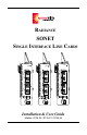
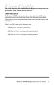
RADIANCE SONET SINGLE INTERFACE LINE CARDS OC-12 R X OC-3 OC-3 PWR PWR PWR LK R X LK R X M M M M M M T X T X T X R X LK R X LK R X S M S M L H T X T X T X Installation & User Guide Models: R125-34 / R125-37 / R135-34 LK LK
Radiance SONET Single Interface Line Cards Fiber to Fiber: R125-34 ________ OC-3/STM-1 multimode SC to singlemode SC R125-37 ________ OC-3/STM-1 multimode SC to singlemode SC (40 km) R135-34 ________ OC-12/STM-4 multimode SC to singlemode SC This publication is protected by the copyright laws of the United States and other countries, with all rights reserved.
Table of Contents Radiance SONET Single Interface Line Cards Installation & User Guide Overview ............................................................................................................. 4 Installation Guide ............................................................................................... 5 STEP 1: Unpack the Line Card ........................................................... 5 STEP 2: Set the DIP Switches .............................................................
Overview The Radiance SONET single interface line card provides seamless integration between fiber optic multimode and singlemode segments in OC-3/ STM-1 or OC-12/STM-4 networks. Use the card’s singlemode connector to extend your network reach up to 40 km. The Radiance line card is manageable through console commands, Metrobility’s GUI-based NetBeacon® or WebBeacon software, or any SNMP application.
Installation Guide Follow the simple steps outlined in this section to install and start using your Radiance SONET single interface line card. NOTE: Electrostatic discharge precautions should be taken when handling any line card. Proper grounding is recommended (i.e., wear a wrist strap). 1 Unpack the Line Card 2 Set the DIP Switches* Your order has been provided with the safest possible packaging, but shipping damage does occasionally occur. Inspect your line card carefully.
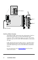
ON OFF F C LL LL LL R R1 2 DIP switches 1000BASE PWR SX R X LK M M Port 1 T X LK R X Port 2 S M T X LX Power Connector Link Loss Return Switches The Radiance SONET single interface line card incorporates Link Loss Return (LLR) functionality as an aid in troubleshooting remote connections. LLR is enabled independently on each port. When LLR is enabled on a port, loss of its receive (RX) link disables its own transmit (TX) link.
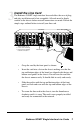
3 Install the Line Card The Radiance SONET single interface line card offers the ease of plugand-play installation and is hot-swappable. All cards must be firmly secured to the chassis before network connections are made. Follow the simple steps outlined below to install your line card.
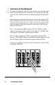
4 Connect to the Network To connect the Radiance line card to the network, insert the fiber optic cables into the appropriate SC connectors. (See the figure below.) Be sure the card is secured to the chassis before making network connections.
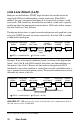
User Guide This section contains more information regarding the operating features of the Radiance SONET single interface line card. LED Indicators The Radiance SONET single interface line card provides three LEDs on the front panel for the visible verification of unit status and proper functionality. These LEDs can assist with troubleshooting and overall network diagnosis and management. When lit, the LEDs indicate the following status: • PWR (power): The unit is powered ON.
Link Loss Return (LLR) Both ports on the Radiance SONET single interface line card have been designed with LLR for troubleshooting a remote connection. When LLR is enabled*, the port’s transmitter shuts down if its receiver fails to detect a valid receive link. LLR should only be enabled on one end of a cable and is typically enabled on either the unmanaged or remote device. LLR works with in conjunction with Link Loss Carry Forward.
Link Loss Carry Forward (LLCF) The Radiance SONET single interface line card incorporates LLCF for troubleshooting a remote connection. With LLCF, the ports do not transmit a signal until they receive a signal from the opposite port. For example, if a line card loses link on Port 2, the card will not transmit link pulses out of Port 1. The diagram below shows a typical network configuration with good link status using SONET line cards for remote connectivity.
Topology Solutions Servers Switch PC running Network Management Software Radiance R5000 Central Service Platform with SONET Single Interface Line Cards Workgroup Hub remote connection — singlemode Switch Enterprise Switch Multimode Links Singlemode Links 12 User Guide Enterprise
Technical Specifications Protocol OC-3/ STM-1 OC-12/ STM-4 Fiber Type and Models Wave Length Cable Length MM (R125-34/ 1310nm R125-37) 2km (rated) 15km (rated, SM 1310nm based on (R125-34) power budget) SM LH 40km 1310nm (R125-37) (rated) MM SM 1310nm 1310nm 500m (rated) 15km (rated) Cable Size Core/ Clad RX Input Power (min) RX Input Power (sat) TX Output Power (min) TX Output Power (max) 50µm/ -30dBm -14dBm -23.5dBm -14dBm 125µm 62.
Product Safety, EMC and Compliance Statements This equipment complies with the following requirements: • UL • CSA • EN60950 (safety) • FCC Part 15, Class A • EN55022 Class A (emissions) • EN50082-1 (immunity) • IEC 825-1 Classification • Class 1 Laser Product • DOC Class A (emissions) This product shall be handled, stored and disposed of in accordance with all governing and applicable safety and environmental regulatory agency requirements.
Warranty and Servicing Three-Year Warranty for Radiance SONET Single Interface Line Card Metrobility Optical Systems, Inc. warrants that every Radiance SONET single interface line card will be free from defects in material and workmanship for a period of THREE YEARS from the date of Metrobility shipment. This warranty covers the original user only and is not transferable.
Product Manuals The most recent version of this manual is available online at http://www.metrobility.com/support/manuals.htm Product Registration To register your product, go to http://www.metrobility.com/support/registration.asp 25 Manchester Street, Merrimack, NH 03054 USA tel: 1.603.880.1833 • fax: 1.603.594.2887 www.metrobility.