
Specifications


Command Line Interface
16
•
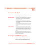
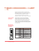
Grasp the edges of the card by the front panel as shown.
•
Line the edges of the card with the slot guides and slide
the card in until the edges are flush and even with the
front of the unit. Do not force the card into the slot
unnecessarily. It should slide in easily and evenly.
•
Secure by turning the thumb screw clockwise until snug.
The card is now ready for connection to the network.
Connect to the Network
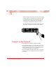
The management card supports 10Base-T Ethernet.
•
Using a standard Category 3 or 5 UTP cable, connect the
management card to your network. Connect Port 1 to your
network. Although the port can be configured for either full
or half duplex, half duplex is recommended.
•
Using the supplied null-modem console cable, connect the
male DB-9 port on the management card to the serial port
on your PC.
PWR
M
M
OC-12
R
X
LK
LK
T
X
S
M
R
X
T
X
LK
LK
S
M
M
M
MGT-10
LK
AT
C
O
N
S
O
L
E
T
P
PWR
A
B
R
ER
SX
LK
PWR
M
M
1000BASE
R
X
LX
LK
S
M
T
X
100 BASE
LK
AT
LK
AT
PWR
R
X
TX
FX
T
X
100 BASE
LK
AT
LK
AT
PWR
R
X
TX
FX
T
X
10 BASE
LK
AT
LK
AT
PWR
R
X
TP
FL
T
X
100 BASE
LK
AT
LK
AT
PWR
R
X
S
M
T
X
R
X
M
M
T
X
100 BASE
LK
AT
LK
AT
PWR
R
X
S
M
T
X
R
X
T
X
M
M
100 BASE
M
A
I
N
P
R
I
S
E
C
RESET
LK
AT
LK
AT
LK
AT
SEC
PWR
SW
100 BASE
redundant twister
“
MAIN
RESET
LK
AT
PRIMARY
LK
AT
SECONDARY
LK
AT
R
X
T
X
R
X
T
X
PWR
SW
100 BASE
LK
AT
LK
AT
PWR
R
X
T
X
R
X
M
M
S
M
T
X
10 BASE
LK
AT
LK
AT
PWR
R
X
TP
FL
T
X
100 BASE
LK
AT
LK
AT
PWR
R
X
T
X
M
M
R
X
T
X
S
M
100 BASE
redundant twister
“
MAIN
RESET
LK
AT
PRIMARY
LK
AT
SECONDARY
LK
AT
R
X
T
X
R
X
T
X
PWR
SW
Card Guide
IMPORTANT!
Tighten thumb screw
to secure each card firmly
to platform before making
network connections.
Blank Panel
Thumb Screw
Management
Card
MGT-10
1
LK
AT
PWR
ER
C
O
N
S
O
L
E
A
B
R
2
LK
AT