
User guide


6 Installation Guide
2
Installation Guide
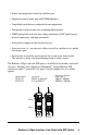
Follow the steps outlined in this section to install and start using the Radiance
1Gbps interface line card with SFP optics.
NOTE: Electrostatic discharge precautions should be taken when handling any
line card. Proper grounding is recommended (i.e., wear a wrist strap).
Unpack the Line Card
Your order has been provided with the safest possible packaging, but
shipping damage does occasionally occur. Inspect your order carefully
for damage that may have occurred during shipment. If you discover
any shipping damage, notify the carrier and follow their instructions for
damage and claims. Save the original shipping carton if return or storage
of the unit is necessary.
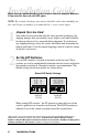
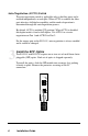
Set the DIP Switches
A set of DIP switches is located on the back of the line card. These
switches are used to enable/disable functions and are clearly marked on
the printed circuit board. Unmarked switches are nonfunctional. The
default settings for the two models are shown below.
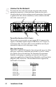
Default DIP Switch Settings
DOWN
UP
65432
LLR1
LLCF
AUTO2
AUTO1
1
DOWN
UP
65432
LLR2
CLCF
AUTO2
1
LLR2
R153-1S R153-SS
(TX-FX) (FX-FX)
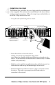
When setting DIP switches
*
, the UP position is when the lever of the
switch is pushed away from the circuit board. The DOWN position is
when the lever of the switch is pushed toward the circuit board.
1
* DIP switches can also be managed via console commands or through Metrobility NetBeacon or
WebBeacon management software. Refer to the
Command Line Interface Reference Guide
,
NetBeacon Element Management Software Installation & User Guide
or
WebBeacon Management
Software Installation & User Guide
for software management information.