
User guide

14 Installation Guide
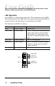
Link Loss Return (LLR)
The fiber ports on the Radiance 1Gbps interface line card have been designed
with Link Loss Return functionality for troubleshooting remote connections.
When LLR is enabled
*
, the port’s transmitter shuts down if its receiver fails to
detect a valid link signal. LLR should only be enabled on one end of a cable and
is typically enabled on either the unmanaged or remote device. LLR works in
conjunction with LLCF and CLCF.
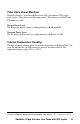
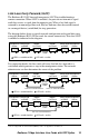
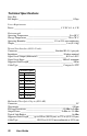
The diagram below shows a typical network configuration with good link status
using two Radiance line cards for remote connectivity. Note that LLR and LLCF
are enabled as indicated in the diagram.
*Units are shipped with the LLR disabled (DOWN).
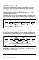
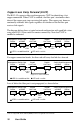
Example: If one of the optical conductors breaks (as shown in the diagram box
below), Gigabit Line Card B, with LLR2 enabled, will return a no-link condition
to its link partner, Line Card A. Using two R153-SS cards with LLCF enabled
on both cards, the no-link condition is carried forward to the switch/hub where a
trap is generated to the management station. The network administrator can then
determine the source of the loss.
Management
Station
Remote
Station
Switch/Hub
w/SNMP
Switch/Hub
w/SNMP
Remote
Cable
LED lit = established link LED unlit = no link
LLCF is ON
LLR2 is ON
LLR1 is OFF
LLCF is ON
LLR2 is ON
LLR1 is OFF
Port 2 Port 1
Port 2 Port 1
Gigabit
Line Card A
Gigabit
Line Card B
Management
Station
Remote
Station
Switch/Hub
w/SNMP
Switch/Hub
w/SNMP
Link Loss Returned
Link Loss Carried Forward
Link Loss Carried Forward
LED lit = established link LED unlit = no link
Broken
Conductor
LLCF is ON
LLR2 is ON
LLR1 is OFF
LLCF is ON
LLR2 is ON
LLR1 is OFF
Port 2
Port 1
Gigabit
Line Card A
Gigabit
Line Card B
IMPORTANT: LLR must not be active on both ends of the same cable. If it is,
the link can never be established.