
User guide

12 Installation Guide
User Guide
This section contains information regarding the operating features of the
Radiance 1Gbps interface line card with SFP optics.
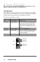
LED Operation
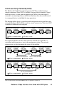
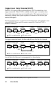
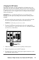
Several LEDs are visible from the front panel. These include the power (PWR),
link (LK) and activity (AT) LEDs. There are separate link and activity LEDs for
each port. Refer to the table below for a description of each LED.
The function of each LED is as follows:
LED Label Color (Status) Indication
PWR Green (steady) Power is ON.
(Port 1) LK Green (steady) Port 1 is receiving a valid link integrity
signal. Link signals are derived from
idle symbols for a copper port or the
presence of an optical signal for a fiber
port.
(Port 1) AT Green (blinking) Port 1 is receiving data.
(Port 2) LK Green (steady) Port 2 is receiving a valid link integrity
signal (i.e., the presence of an optical
signal is detected).
(Port 2) AT Green (blinking) Port 2 is receiving data.
Port 1
Port 2
1000 BASE
LK
AT
LK
AT
P
W
R
1
2
Power LED
Link LED
Activity LED
Activity LED
Link LED