
User guide

Radiance 1000Mbps Redundant Interface Line Cards 7
2
Installation Guide
Follow the steps outlined in this section to install and start using your Radi-
ance 1000Mbps redundant interface line card.
NOTE: Electrostatic discharge precautions should be taken when handling any
line card. Proper grounding is recommended (i.e., wear a wrist strap).
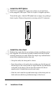
Unpack the Line Card
Your order has been provided with the safest possible packaging, but
shipping damage does occasionally occur. Inspect your order carefully
for damage that may have occurred during shipment. If you discover
any shipping damage, notify the carrier and follow their instructions for
damage and claims. Save the original shipping carton if return or storage
of the unit is necessary.
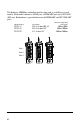
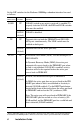
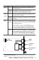
Set the DIP Switches
A set of DIP switches, located on the circuit board, provides configura-
tion options for several modes of operation. These switches are clearly
marked on the line card’s printed circuit board. Refer to the tables on
the following pages for the proper setting of the DIP switches.
*
The DIP switches are the same on all models except for switches 4 and
5. On the R752-11, both switches are non-functional. On the R752-1S,
switch 5 controls Copper Loss Carry Forward (CLCF); and on the
R752-SS, switch 5 controls Link Loss Carry Forward (LLCF).
1
* DIP switches can also be managed via console commands or through Metrobility NetBeacon or
WebBeacon management software. Refer to the
Command Line Interface Reference Guide
,
NetBeacon Element Management Software Installation & User Guide
or
WebBeacon Management
Software Installation & User Guide
for software management information.
DOWN
UP
65432
RED
LLCF
LINK
AUTO
TX
1
SONR
DOWN
UP
65432
RED
CLCF
LINK
AUTO
TX
1
SONR
DOWN
UP
65432
RED
AUTO
TX
1
SONR
R752-11 R752-1S R752-SS
Default DIP Switch Settings