
User guide


10 Installation Guide
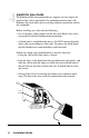
Apply Power to the Chassis
IMPORTANT
• Turn off the DC voltage source before beginning.
• Connect the wire leads to the chassis before applying power.
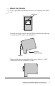
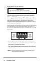
The DIN rail chassis provides two input power supply connections,
PWR A and PWR B. The two power supplies support redundant power,
however, there is no load distribution. With redundant power, if the
source to PWR A or B fails, the other source automatically provides the
entire power load for the chassis. An input power supply may be
removed or replaced without interrupting chassis operations as long as
the other input is providing power.
Power connectors are located below the front panel of the main housing
unit. The inputs have screw-down terminal blocks that support 24 V
DC at 0.75 A. Connect the chassis only to a UL listed Class “2” or LPS
power source.
24VDC
.75A
CLASS 2
24VDC
.75A
CLASS 2
PWR A
PWR B
—
+
+
—
• Connect the wire leads from the voltage source to the appropriate
terminals and tighten the screws. For redundant power, connect each
power supply to a separate power source.
• Verify proper connection and operation using the PWR LED on the
installed card(s).
Caution: The center terminal connector provides grounding for the
chassis and must be maintained.
6