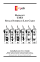
RADIANCE T3/E3 SINGLE INTERFACE LINE CARDS T3 T3 E3 T X T X R X T X LBK MM LBK LBK LK LK LK T X T X LBK SM LBK R X LK LK T X LK R X R X LBK R X R X LK T X LK LK R X LBK PWR T X LK R X LBK PWR T X LK R X R X PWR T X LK E3 T3 E3 PWR PWR PWR LBK MM LBK SM LBK BWDM Installation & User Guide Models: R115-23 / R115-24 / R115-25 / R115-26 / R115-27 / R115-2J / R115-2X / R115-2Y / R175-23 / R175-24 / R175-25 / R175-26 / R175-27 / R175-2J / R175-2X / R175-2Y L
Radiance T3/E3 Single Interface Line Cards T3 Copper to T3 Fiber: R115-23 _____ R115-24 _____ R115-25 _____ R115-26 _____ R115-27 _____ R115-2J ______ R115-2X _____ T3 BNC to T3 multimode SC T3 BNC to T3 singlemode SC T3 BNC to T3 multimode ST T3 BNC to T3 singlemode ST T3 BNC to T3 singlemode SC (40km) T3 BNC to T3 singlemode SC (100km) T3 BNC to T3 singlemode SC 1550/1310nm bidirectional wavelength division multiplexed (BWDM) R115-2Y _____ T3 BNC to T3 singlemode SC 1310/1550nm BWDM E3 Copper to E3 Fibe
Table of Contents Radiance T3/E3 Single Interface Line Cards Installation & User Guide Overview ............................................................................................................... 4 Installation Guide ................................................................................................ 5 STEP 1: Unpack the Line Card ..................................................................... 5 STEP 2: Set the Switches .........................................................
Overview The Metrobility® Radiance T3/E3 line card provides high-speed integration and conversion of T3 (44.736Mpbs) or E3 (34.368Mbps) coaxial telco communication lines to fiber transport environments. The copper data stream is converted to optical signals for greater noise immunity and longer transmission. The T3/E3 line card supports remote fiber optic links up to 2km over multimode and up to 100km over singlemode cable.
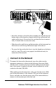
Installation Guide Follow the simple steps outlined in this section to install and start using your Radiance T3/E3 single interface line card. NOTE: Electrostatic discharge precautions should be taken when handling any line card. Proper grounding is recommended (i.e., wear a wrist strap). 1 Unpack the Line Card 2 Set the Switches Your order has been provided with the safest possible packaging, but shipping damage does occasionally occur. Inspect your order carefully.
LBO Switch (functional only on T3 cards) Set the Line Build Out (LBO) switch up to support a long haul connection if the length of your coaxial cable is between 255 and 1200 feet. Set LBO down to support a short haul connection if the length of your coaxial cable is between 0 and 255 feet. The default setting is short haul. CLP Switch The Copper Loopback (CLP) switch enables/disables loopback on the copper port.
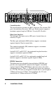
Slot for Management Card Card Guide 10/100 10/100 PWR 100 T1 PWR RX LK 100 TX RX RX M M LK LK LBK x II TX x II TX RX RX LK T X R X LK RX LK T X M M LK T X x II TX LBK LK RX R X LK LX RX M M LK 100 FD LK S M M M LK M M OC-12 LK TX LK TX TX L H R X TX LK R X RX M M T X T X T X LK 1 AT LK 2 AT TX RX RX RX LK R X LK M M R X M M PWR M M T X LK LBK FX M M LK FX M M LK TX TX LBK FX LK M M LK R X S M LK T X MGT-10 PWR PWR
10/100 PWR LK x II x II LK FD RX ALM LBK LBK 100 T X PWR 100 T X TX RX RX LK LK R X x II T3 LBK LBK x II TX TX 10/100 PWR PWR PWR PWR 10/100 100 BASE 10/100 10/100 MGT-10 PWR PWR FL T X 100 LBK FX TX RX T X LK R X LK LK x II TX FL FD RX T X M M 100 FD RX LK ALM LK R X 10/100 PWR PWR MAN FD RX T X T1 10/100 PWR FD RX LK FX FX E3 PWR MAN R X M M AT 100 1 RX AT T X M M LK LK LK 2 T X x II LK FD RX LK TX TX x II AT T
User Guide This section contains more detailed information regarding the operating features of the Radiance T3/E3 single interface line card. LED Indicators The Radiance T3/E3 single interface line card provides several LEDs for the visible verification of unit status and proper functionality. These LEDs can aid in troubleshooting and overall network diagnosis and management. System LED LED Label Color/ Status Indication Green Unit is receiving power. OFF Unit is not receiving power or has failed.
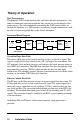
Theory of Operation Data Transparency The Radiance T3/E3 single interface line card offers full data transparency. Any codes or commands contained within the data stream are passed through to the remote device. The only commands executed by the T3/E3 card are those set through the hardware (i.e., DIP switches) or software, which communicates with the card via the management bus on the chassis backplane.
Timing Paths The transmit (TX) and receive (RX) paths are clocked independently and during normal operation, the Radiance T3/E3 line cards are never timing masters of the network system. In the coaxial to fiber path, timing is recovered by the card’s LIU and transmitted over the fiber line to the remote T3/E3 line card. In the fiber to coaxial path, timing is derived from the incoming optical signal and sent over the coaxial TX line.
Factory Settings Default Hardware Settings Copper Loopback .................................................................................... Disabled Fiber Loopback ........................................................................................ Disabled Line Build Out (T3 models only) ......................................... Short Line (0-255 ft) The hardware DIP switches can be overridden through software.
Local T3/E3 Card with Fiber Port Disabled Local Device Receives All 1s Coax All Ones green LED Remote T3/E3 Fiber Port Detects No Link LK LK LK Fiber LK Remote Device Receives All 1s All Ones Coax unlit LED Once a port is disabled, the only way to enable it again is through software. Through SNMP management, NetBeacon or WebBeacon*, you can view the following information for the Radiance T3/E3 line card.
Link Loss Indications The following examples show the status of the LK LED under various link conditions and describe when unframed all ones (AIS for E3 only) are generated. (Loopback is disabled in these examples.) Normal The diagram below shows a typical configuration with good link status. Local T3/E3 Line Card Local Device Remote T3/E3 Line Card LK LK Coax Fiber Coax LK LK green LED Remote Device unlit LED Input Coaxial Link Loss Loss of the copper input disables the BNC port’s LK LED.
Remote Output Coaxial Link Loss Loss of link to the remote device produces a red alarm condition at the remote site and should force the device to revert to its internal clock. If the remote device is configured to send back a yellow alarm (AIS) under this condition, the two Radiance T3/E3 line cards will carry the alarm forward to the local device, as shown below.
Loopback Modes The Radiance T3/E3 line card features two loopback modes to help verify correct installation and to diagnose system problems. Normal During normal operation, without loopback, data from a local device (CSU, PBX, etc.) enters the local T3/E3 line card’s coaxial receiver, passes through the fiber line between the two cards, then exits the remote card’s coaxial transmitter to enter the remote equipment, and vice versa.
Local Device Coax Fiber Coax Remote Device Remote T3/E3 Card Local T3/E3 Card with Copper Loopback X Fiber Loopback In this mode, the incoming data and clock on the fiber line are looped back. The loop occurs in the FPGA. The data is still sent out the coaxial transmitter. However, the data received at the BNC interface is ignored. In the diagram below, the remote T3/E3 line card has fiber loopback enabled.
Topology Solutions The Radiance T3/E3 single interface line card is a point-to-point media converter designed to extend the reach of copper T3/E3 links and to provide protection from power surges and electromagnetic interference. Each T3/E3 line card supports a single remote T3/E3 card.
Technical Specifications Network Connections Coaxial Interface Connector __________________________________________ BNC receptacle Impedance ________________________________________________ 75 ohms Signal Structure ____________________________ ANSI T1.404, T1404a (T3) _____________________________________ ITU G.
Singlemode Fiber Optic Interface — extended long haul distance support Connector _____________________________________________________ SC Wavelength _______________________________________________ 1550 nm RX Input Sensitivity ________________________________ -37 dBm minimum Output Power ___________________________ -3.0 dBm to 0 dBm (9/125 µm) Supported Link Length _________________________ up to 100 km full duplex Cable Type ______________________ 8.3/125, 8.
Acronyms and Abbreviations This list defines the acronyms and abbreviations used in this guide. AIS B3ZS BNC BWDM CLP CSU DSU E3 F/O FLP FPGA HDB3 LBK LBO LIU LK Mbps MM MTBF NRZ PBX PWR RX SM SNMP T3 TX VCXO Alarm Indication Signal Bipolar Three Zeroes Substitution T3 line coding Bayonet-Neill-Concelman connector Bidirectional Wavelength Division Multiplexed Copper Loopback Channel Service Unit Data Service Unit 34.
Product Safety, EMC and Compliance Statements This equipment complies with the following requirements: • UL • ITU-G.703 • CSA • G.704 • EN60950 (safety) • G.706 • FCC Part 15, Class A • ANSI T1.403-1999 • EN55022 Class A (emissions) • ANSI T1.408 • EN55024: 1998 (immunity) • Class 1 Laser Product • DOC Class A (emissions) • IEC 825-1 Classification This product shall be handled, stored and disposed of in accordance with all governing and applicable safety and environmental regulatory agency requirements.
Warranty and Servicing Three-Year Warranty for Radiance T3/E3 Single Interface Line Card Metrobility Optical Systems, Inc. warrants that every Radiance T3/E3 single interface line card will be free from defects in material and workmanship for a period of THREE YEARS from the date of Metrobility shipment. This warranty covers the original user only and is not transferable.
Product Manuals The most recent version of this manual is available online at http://www.metrobility.com/support/manuals.htm Product Registration To register your product, go to http://www.metrobility.com/support/registration.asp 25 Manchester Street, Merrimack, NH 03054 USA tel: 1.603.880-1833 • fax: 1.603.594.2887 www.metrobility.