
User manual

30 Wattmeters
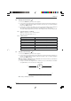
3.4.3 Apparent power measurements
1. Press the ON/OFF key: the first screen appears
2. Connect the measurement leads to the instrument’s current measurement terminals
(on the left), complying with the polarities indicated: red lead on the “+” terminal and
black lead on the “COM” terminal.
Connect the measurement leads to the instrument’s voltage measurement terminals
(on the right), complying with the polarities indicated: red lead on the “+” terminal
and black lead on the “COM” terminal.
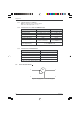
3. Set up as indicated in the connection diagrams in Fig.4.4.1 (single phase) or Fig.4.4.2
(balanced three-phase, T3FE only PX 120), depending on the case, making sure if
possible that the maximum acceptable limits are not exceeded (see table below).
Range switching is automatic.
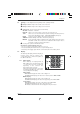
4. The upper digital display indicates the value of the voltage and the corresponding unit (V).
The middle digital display indicates the value of the current and the corresponding unit (A).
The lower digital display indicates the active power (W)
Press the DISPLAY key to display the 2nd screen:
The middle digital display indicates the value of the apparent power and the
corresponding unit (VA).
■■
■■
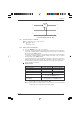
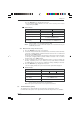
■ Characteristics
Display range 1000 VA 6 kVA
Measuring range 10.0 VA...999.9 VA 1000 VA...5999 kVA
Accuracy at 50 Hz for cos ϕ =1 2% of reading ±2 cts 2% of reading ±2 cts
Resolution 0.1 VA 1 VA
Display stability 5 counts in normal mode
2 counts in SMOOTH mode
Display response time 400 ms in normal mode
3 s in single-phase in SMOOTH mode
Note 1: The measurement of the apparent power is a signed measurement.
Above 6 kVA +10%, the display indicates “OL”.
Note 2:In three-phase, the active power measurement may be inaccurate for non-
sinusoidal signals.
3.4.4Reactive power measurements
1. Press the ON/OFF key: the first screen appears.
2. Connect the measurement leads to the instrument’s current measurement terminals
(on the left), complying with the polarities indicated: red lead on the “+” terminal and
black lead on the “COM” terminal.
Connect the measurement leads to the instrument’s voltage measurement terminals
(on the right), complying with the polarities indicated: red lead on the “+” terminal
and black lead on the “COM” terminal.
3. Set up as indicated in the connection diagrams in Fig.4.4.1 (single phase) or Fig.4.4.2
(balanced three-phase, T3FE only PX 120), depending on the case, making sure if
possible that the maximum acceptable limits are not exceeded (see table below).
Range switching is automatic.
4. The upper digital display indicates the value of the voltage and the corresponding
unit (V).
The middle digital display indicates the value of the current and the corresponding
unit (A).
The lower digital display indicates the active power (W)
Chapter III