
User manual

29Wattmeters
L1
W
L1
L2
L2
L3 L3
U U
I
I
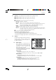
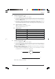
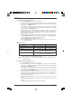
Fig 4.4.2 Three-phase/balanced wires (T3FE)
connection diagram (PX 120 only)
3.4.1Specific reference conditions
DC: AC component < 0.1% of the DC signal
AC: - Sinusoidal signals
- PF = 1
- Frequency: 50 Hz
3.4.2 Active power measurements
1. Press the ON/OFF key: the first screen appears
2. Connect the measurement leads to the instrument’s current measurement terminals
(on the left), complying with the polarities indicated: red lead on the “+” terminal and
black lead on the “COM” terminal.
Connect the measurement leads to the instrument’s voltage measurement terminals
(on the right), complying with the polarities indicated: red lead on the “+” terminal
and black lead on the “COM” terminal.
Set up as indicated in the connection diagrams in Fig.4.4.1 (single phase) or Fig.4.4.2
(balanced three-phase, T3FE only PX 120), depending on the case, making sure if
possible that the maximum acceptable limits are not exceeded (see table below).
Range switching is automatic.
■■
■■
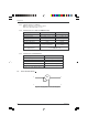
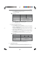
■ Characteristics
Display range 1000 W 6 kW
Measuring range 10.00 W...999.9 W 1000 W...5999 kW
Accuracy 1% of reading ±2 cts 1% of reading ±2 cts
Accuracy for DC 2% of reading ±3 cts 2% of reading ±3 cts
Resolution 0.1 W 1 W
Display stability 5 counts in normal mode
2 counts in SMOOTH mode
Response time 400 ms in normal mode
of the display 3 s in single-phase, in SMOOTH mode
Note 1
:
The measurement of the active power is a signed measurement.
Above 6 kW +10%, the display indicates “OL”.
Note 2: In three-phase, the active power is only measured on the fundamental
components so it is only valid for sinusoidal signals.
Chapter III