
User's Guide
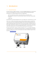
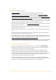
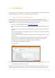
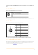
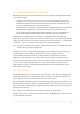
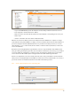
Table Of Contents
- Remote Terminal Unit M717
- Table Of Contents
- Introduction
- Installation
- Register the RTU to the M2M Gateway
- The SDI Connector
- The MPI Connector
- The Micro USB Service Connector
- About the Data Acquisition Subsystem
- SDI-12 Sensors
- Create a New Template From an Existing One
- Create a New Template From Scratch
- Interface to a Davis Vantage Pro Console
- Interface to a Thies TDL14 or DL16 Data Logger
- Mechanical Installation
- Operation
- Configuration
- Commands
- General Commands
- help
- ver
- echo
- ps
- date
- log
- attr
- pin
- hwid
- connect
- xfer
- fwupdate
- reboot
- exit
- Data Acquisition Commands
- dacq
- dacq info
- dacq sample
- dacq retrieve
- dacq abort
- dacq date
- dacq interval
- dacq direct
- dacq t
- hist
- hist info
- hist stat
- hist map
- hist purge
- Data Acquisition Legacy Commands
- sdi t
- thi t
- thi direct
- Communication Commands
- net
- net get
- net up
- net down
- net session
- modem
- modem direct
- modem pwrdown
- modem pwrup
- modem reset
- modem mode
- File System Commands
- ls
- mkdir
- cd
- cp
- pwd
- rm
- cat
- Command Line Interface Error Messages
- Attributes
- Technical Specifications

templates are available on the M2M Gateway, while new sensors/templates can be easily defined by the
user.
2.2. The SDI Connector
The pin-out of the SDI-12/RS-485 connector is shown below.
Note: The colours given in the last column are valid for the standard Metrilog M12 cable (option). Pin 3 is not
used in native SDI-12 mode.
2.3. The MPI Connector
The pin-out of the Multi Protocol Interface (MPI) is given below.
Note: The colours given in the last column are valid for the standard Metrilog M12 cable (option).
2.4. The Micro USB Service Connector
The USB connector is used for maintenance and service. You should not have to deal with this connector
unless indicated so by the Metrilog support personnel. For additional information on the use of this
connector, check also the “Commands” section of this manual.
1
Brown
+ Vin (6 to 30 Volt)
2
White
- Vin and SDI-12 GND
3
Blue
RS-485 A/CAN-L (unused in native SDI-12 mode)
4
Black
SDI-12/RS-485 B/CAN-H
12
3 4
1
White
- Vin and GND
2
Brown
+ Vin (6 to 30 Volt)
3
Green
RS-232 RxD/RS-485 A
4
Yellow
RS-232 TxD/RS-422 Z
5
Grey
RS-485 B
6
Pink
RS-232 GND
7
Blue
RS-422 Y
8
Red
GND/Shield
12
3
4
5
6
7
8
6