
User's Guide
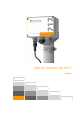
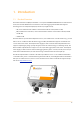
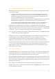
Table Of Contents
- Remote Terminal Unit M717
- Table Of Contents
- Introduction
- Installation
- Register the RTU to the M2M Gateway
- The SDI Connector
- The MPI Connector
- The Micro USB Service Connector
- About the Data Acquisition Subsystem
- SDI-12 Sensors
- Create a New Template From an Existing One
- Create a New Template From Scratch
- Interface to a Davis Vantage Pro Console
- Interface to a Thies TDL14 or DL16 Data Logger
- Mechanical Installation
- Operation
- Configuration
- Commands
- General Commands
- help
- ver
- echo
- ps
- date
- log
- attr
- pin
- hwid
- connect
- xfer
- fwupdate
- reboot
- exit
- Data Acquisition Commands
- dacq
- dacq info
- dacq sample
- dacq retrieve
- dacq abort
- dacq date
- dacq interval
- dacq direct
- dacq t
- hist
- hist info
- hist stat
- hist map
- hist purge
- Data Acquisition Legacy Commands
- sdi t
- thi t
- thi direct
- Communication Commands
- net
- net get
- net up
- net down
- net session
- modem
- modem direct
- modem pwrdown
- modem pwrup
- modem reset
- modem mode
- File System Commands
- ls
- mkdir
- cd
- cp
- pwd
- rm
- cat
- Command Line Interface Error Messages
- Attributes
- Technical Specifications

1. Introduction
1.1. Product Overview
The Remote Terminal Unit (RTU) model M717 is a low power GSM/GPRS/UMTS/LTE based communication
device, that includes flexible bus/serial interfaces and a data-logging unit. The M717 RTU supports
following protocols and Input/Output (I/O) interfaces (see figure below):
•
SDI, can be switched under software control between SDI-12 native, RS-485 or CAN;
•
MPI, or Multi Protocol Interface; can be switched under software control between RS-232, RS-422
and RS-485;
•
USB micro AB.
The M717 RTU can operate with multiple data sources, even simultaneous on both interfaces (e.g., several
SDI-12 sensors on SDI and a Thies DL16 data logger on MPI). The M717 RTU supports a maximum of 50
sensors with a total of max. 128 sampled values (tags) per data record. The SDI-12 implementation also
supports output tags by using specially designed, custom “X” commands (e.g., for switching valves). The
Davis and Thies implementations support one sensor (the data logger) with a total of max. 128 sampled
values (tags) per data record. The internal data logging memory (FIFO—First In, First Out) can store up to
half a million individual values, the older values being overwritten when the memory fills up.
The SDI-12 implementation conforms to the SDI-12 specification version 1.3. For additional information
on the SDI-12 bus, please consult the following document: “SDI-12, A Serial-Digital Interface Standard for
Microprocessor-Based Sensors, Version 1.3”. The document can be found on the SDI-12 Support Group’s
web site at http://www.sdi-12.org.
3