
Operating instructions


60 10/04/2015
Electronic mobile POCLAIN HYDRAULICS
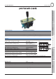
Fitting the main connector
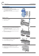
Locking device position
A. Place the black unit on the ECU.
Note its position and separate its from the ECU.
B. Insert the purple locking device into the unit from the botton
to the top and push until it clicks.
The cable will have to be positioned on the locking device
side.
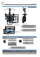
Fitting the connector
1. Unclip the 2 yellow supports.
2. Remove these supports.
3. Turn the unit over.
4. Strip the wire over 4 mm.
Crimp each conductor on its lug using pliers FCI211S005.
5. Insert each lug into the connector as shown in the electrical
circuit diagram in the appendix.
In case of error, use extraction tool 210S048 to remove the
lug.
6. Insert the green plugs into the free ports of the connector.
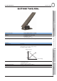
7. Clip on the 2 yellow supports.
8. Position the cover and lower it.
The cover tab (A) must be on the right of the unit tab (B).
9. Lock it by pulling on it until there is a click.
10. Secure the cable uising a cable grip.
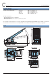
Removing the locking device
12. To remove the purple locking device, press as shown.
13. Partially pull out the locking device, press as shown.
14. Repeat point 12 on the other side, and completely remove
the locking device.