
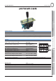
Operating instructions


52 10/04/2015
Electronic mobile POCLAIN HYDRAULICS
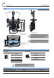
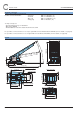
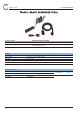
Layout
Electrical wiring
Analog signal Neutral signal
A Signal 1 1 Common
B Ground signal 1 2 Opened contact in neutral
position
C +5 V signal 1 3 Closed contact in neutral
position
D +5 V signal 2 4 Not used
E Signal 2
F Ground signal 2
For SmartDrive
TM
controllers use the analog signal 2
and opened contact in neutral position.
Mating connector kit
Commercial name Part Number
KIT-CONNECT-4-PIN-DEUTSCH A39961L page 78
KIT-CONNECT-6-PIN-MP A38140G page 73
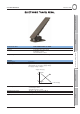
10°
30°
30°
94 [3.70]
107 [4.21]
135 [5.31]
98 [3.86]
130 [5.12]
140 [5.51]
160 [6.30]
55 [2.16]
75 [2.95]
4 x Ø 8,5
[dia. 0.33]
20
[0.79]
M10
Tightening torque
10 Nm ± 2
Forward Reverse
Neutral signal
Analog signal
According to the application, the mounting of
another handle must be validated to avoid that its
weight, its height and the vibrations induce
unexpected movement of the joystick.
Do not remove the Z grid during joystick mounting
because there would be a risk of escape of roller
on switch bracket and breakage of neutral switch
actuator.
F
E
D
C
B
A
1
2
3
4