
Operating instructions


26 10/04/2015
Electronic mobile POCLAIN HYDRAULICS
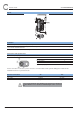
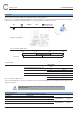
Layout
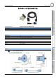
Connection of the encoder
The encoder has a cable with following parameters:
Lenght 2 m
Diameter 5,0 mm + 0,4 mm
Material PUR, shielded cable with 5 wires
Wire section 0,14 mm
2
Function Wire Pulse diagram
Power supply (+Vs) Brown
Square frequency signal A (CHA) Green
Square frequency signal B (CHB) Yellow
Ground (0V) White
Start Top (CHN) Pink
Connected to housing Screen
Phase shift beetween CHA & CHB = 90°
Signal processing recommendation
The encoder is an incremental encoder providing a signal A, B and a start top.
These signals are generated by the encoder for each separate position 3600 times per revolution.
If your counting system monitors only one channel (Channel A, for example) disruption on the line or instability of position
may cause generation of several high level signals on one channel only.
To ensure a correct count of the number of pulse and eliminate these spurious signals,it is important to take into account
the two channels A and B to use the phase to eliminate spurious signals.
A large number of input card or tachometer provides this function by setting "AB 90 ° phase shift."
This feature also prevents any consideration of disturbance.
Such a disturbance could be seen as an encoder pulse if that channel is not correlated through channel B.
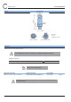
I24
[dia. 0.94]
10,5
[0.41]
SW 2,0
2,2 [0.09]
2 [0.08]
1 [0.04]
44 [1.73]
M4x8
3x120°
I12 H7
[dia. 0.47]
I50 [dia. 1.97]
I58 [dia. 2.28]
I42 [dia. 1.65]
60°
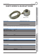
Plastic angular lock
CHA
CHB
CHN
CCW