
Operation Manual


MI 3121H Smartec 2,5 kV Insulation / Continuity Continuity
28
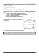
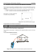
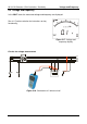
Test circuit for CONT resistance measurement
R
y
S
z
T
x
Figure 5.14: 2-wire test lead application
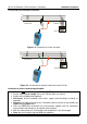
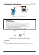
Continuous resistance measurement procedure
Select continuity function RLOW or CONT using the BACK / NEXT keys of
function selector.
Set sub-function CONT.
Enable and set the limit (optional).
Connect test lead to the instrument.
Compensate test leads resistance (if necessary, see section 5.2.3).
Disconnect from mains supply and discharge the object to be tested.
Connect test leads to the tested object (see Figure 5.14).
Press the TEST key to begin performing a continuous measurement.
Press the TEST key to stop measurement.
After the measurement is finished, store the result (optional).
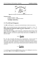
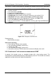
Figure 5.15: Example of continuous resistance measurement
Displayed result:
Resistance.
Note:
Continuous buzzer sound indicates that measured resistance is less than 2 Ω.