
Operation Manual


MI 3121H Smartec 2,5 kV Insulation / Continuity Insulation resistance
22
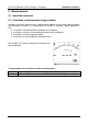
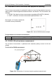
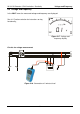
Test circuits for insulation resistance
L1
L2
L3
N
PE
mains voltage
switched off
closed
switches
loads disconnected
Figure 5.2: Connection of 2-wire test lead
L1
L2
L3
N
PE
mains voltage
switched off
closed
switches
loads disconnected
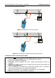
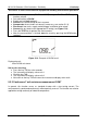
Figure 5.3: Connection of optional 3-wire test lead (A 1319)
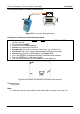
Insulation resistance measuring procedure
Select the INS function using the BACK / NEXT keys of function selector.
Set the required test voltage (Press the TAB key then use arrows).
Enable and set limit value (optional).
Disconnect tested installation from mains supply (and discharge insulation as
required).
Connect test lead to the top of the instrument and to the item to be tested (see
Figure 5.2 and Figure 5.3).
Press the TEST key to perform the measurement (double click for continuous
measurement and later press to stop the measurement).
After the measurement is finished wait until tested item is fully discharged.
Store the result by pressing the MEM key (optional).