
Operation Manual

MI 3121H Smartec 2,5 kV Insulation / Continuity Connector panel
12
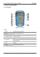
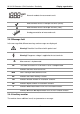
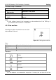
3.2 Connector panel
Figure 3.2: Connector panel
Legend:
1 Test connector Measuring inputs / outputs, connection of measuring cables.
2 Protection cover
Protects from simultaneous access to test connector and power
supply adapter socket / communication connectors.
3 Charger socket Connection of power supply adapter.
4 USB connector Communication with PC USB (1.1) port.
5 PS/2 connector Communication with PC serial port.
Warnings!
Maximum allowed voltage between any test terminal and ground is 600 V!
Maximum allowed voltage between test terminals is 600 V!
Maximum short-term voltage of external power supply adapter is 14 V!