2,5 kV Insulation / Continuity MI 3121H Instruction manual Version 1.2, Code no.
Distributor: Manufacturer: METREL d.d. Ljubljanska cesta 77 1354 Horjul Slovenia web site: http://www.metrel.si e-mail: metrel@metrel.si Mark on your equipment certifies that this equipment meets the requirements of the EU (European Union) concerning safety and electromagnetic compatibility regulations © 2010 METREL The trade names Metrel, Smartec, Eurotest, Autosequence are trademarks registered or pending in Europe and other countries.
MI 3121H Smartec 2,5 kV Insulation / Continuity 1 2 3 4 5 6 7 Table of contents Preface.........................................................................................................................5 Safety and operational considerations.....................................................................6 2.1 Warnings and notes...............................................................................................6 2.2 Battery and charging ...........................................
MI 3121H Smartec 2,5 kV Insulation / Continuity Table of contents 7.3 Periodic calibration ..............................................................................................37 7.4 Service ................................................................................................................37 8 Technical specifications ..........................................................................................38 8.1 Insulation resistance..................................................
MI 3121H Smartec 2,5 kV Insulation / Continuity Preface 1 Preface Congratulations on your purchase of the instrument and its accessories from METREL. The instrument was designed on basis of rich experience, acquired through many years of dealing with insulation and resistance test equipment. The multifunctional hand-held insulation tester Smartec 2,5 kV Insulation / Continuity is intended in general for the following tests and measurements: True r.m.s.
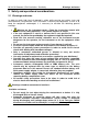
MI 3121H Smartec 2,5 kV Insulation / Continuity Warnings and notes 2 Safety and operational considerations 2.
MI 3121H Smartec 2,5 kV Insulation / Continuity Warnings and notes Notes related to measurement functions: General If there is any irregular condition on input terminals then the selected measurement can't be performed. Insulation resistancecontinuity measurements shall be performed on deenergized objects, i.e. voltage between test terminals should be lower than 10 V! PASS / FAIL indication is enabled when limit is set to ON. Apply appropriate limit value for evaluation of measurement results.
MI 3121H Smartec 2,5 kV Insulation / Continuity Battery and charging 2.2 Battery and charging The instrument uses six AA size alkaline or rechargeable Ni-Cd or Ni-MH battery cells. Nominal operating time is declared for cells with nominal capacity of 2100 mAh. Battery condition is always present on the display when the instrument is turned on. In case the battery is weak, the instrument indicates this as shown in Figure 2.1.
MI 3121H Smartec 2,5 kV Insulation / Continuity Battery and charging 2.2.1 New battery cells or cells unused for a longer period Unpredictable chemical processes can occur during charging of new battery cells or cells that were unused for a longer period (more than 3 months). Ni-MH and Ni-Cd battery cells are affected to capacity degradation (sometimes called as memory effect). As a result, the instrument operation time can be significantly reduced.
MI 3121H Smartec 2,5 kV Insulation / Continuity Standards applied 2.3 Standards applied The MI 3121H Smartec 2,5 kV Insulation / Continuity instrument is manufactured and tested according to the following regulations, listed below.
MI 3121H Smartec 2,5 kV Insulation / Continuity Front panel 3 Instrument description 3.1 Front panel 1 2 3 4 5 6 7 12 11 10 9 8 Figure 3.1: Front panel Legend: 1 2 3 4 5 LCD TEST UP DOWN MEM Store / recall / clear tests in memory of instrument. 6 Function selector Select test function. 7 Backlight 8 ON / OFF 9 CAL Changes backlight level. Switches the instrument power on or off. The instrument automatically turns off 15 minutes after the last key was pressed.
MI 3121H Smartec 2,5 kV Insulation / Continuity Connector panel 3.2 Connector panel Figure 3.2: Connector panel Legend: 1 Test connector 2 Protection cover 3 Charger socket 4 USB connector 5 PS/2 connector Measuring inputs / outputs, connection of measuring cables. Protects from simultaneous access to test connector and power supply adapter socket / communication connectors. Connection of power supply adapter. Communication with PC USB (1.1) port. Communication with PC serial port.
MI 3121H Smartec 2,5 kV Insulation / Continuity 3.3 Back panel Figure 3.3: Back site Legend: 1 2 3 4 5 6 Side belt Battery compartment cover Fixing screw for battery compartment cover Back panel information label Holder for inclined position of the instrument Magnet for fixing instrument close to tested item Figure 3.4: Battery compartment Legend: 1 2 3 Battery cells Serial number label Fuse Size AA, alkaline or rechargeable NiMH / NiCd M 0.
MI 3121H Smartec 2,5 kV Insulation / Continuity Display organization 3.4 Display organization Function field Result field Analog results display Test voltage selection field Figure 3.5: Typical display Message field CAL LIM MEM RCL LOC OBJ PI DAR Auxiliary monitor Battery indication 3.4.1 Function field The function field displays currently selected function. Selected function is Insulation resistance. Selected function is 7 mA Continuous resistance measurement.
MI 3121H Smartec 2,5 kV Insulation / Continuity Display organization Numeric readout of measurement result Measurement result is inside pre-set limits (PASS). Measurement result is out of pre-set limits (FAIL). Analog presentation of measured result. … 3.4.3 Message field In the message field, different warnings and messages are displayed. Warning! Read the User Manual with special care! Warning! Dangerous voltage is applied to the test terminals. Measurement is implemented.
MI 3121H Smartec 2,5 kV Insulation / Continuity Display organization 3.4.5 Battery indication In the menu line, the name of the selected function is displayed. Additional information about active cursor / TEST keys and battery condition are shown. Battery capacity indication. Low battery. Battery is too weak to guarantee correct result. Replace or recharge the battery cells. Recharging in progress (moving segments if power supply adapter is connected). 3.4.
MI 3121H Smartec 2,5 kV Insulation / Continuity Instrument set and accessories 3.5 Instrument set and accessories 3.5.1 Standard set Instrument MI 3121H Instruction manual Calibration certificate 2.5 kV test lead, 2 x 1.5 m Test probe, 2 pcs Crocodile clip, 2 pcs NiMH battery cell, type AA, 6 pcs Power supply adapter CD with instruction manual, and “Guide for testing and verification of low voltage installations” handbook Soft hand strap 3.5.
MI 3121H Smartec 2,5 kV Insulation / Continuity Function selection 4 Instrument operation 4.1 Function selection For selecting test function, the FUNCTION SELECTOR shall be used. Keys: Select test / measurement function: FUNCTION SELECTOR (BACK / NEXT) UP/DOWN TAB TEST MEM CAL Voltage and frequency and phase sequence. Insulation resistance measurement. Resistance to earth connection and equipotential bonding / continuous resistance measurement.
MI 3121H Smartec 2,5 kV Insulation / Continuity Settings 4.2 Settings The instrument offers additional functions by the following combinations of the keys during power on. Combinations are: UP + ON TAB + ON Opens settings menu. Resets the instrument to initial factory settings. Different instrument options can be set in the settings menu. Options are: Setting the instrument to initial values, Setting the date and time. Figure 4.
MI 3121H Smartec 2,5 kV Insulation / Continuity Settings The default setup is listed below: Instrument setting Default value Function Sub-function Insulated resistance Continuity RLOW CONT Parameters / limit value No limit, Utest = 500 V RLOW No limit No limit Note: Initial settings (reset of the instrument) can be recalled also if the TAB key is pressed while the instrument is switched on. 4.2.2 Date and time Selecting this option will allow the user to set the date and time of the unit.
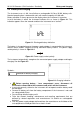
MI 3121H Smartec 2,5 kV Insulation / Continuity Insulation resistance 5 Measurements 5.1 Insulation resistance 5.1.1 Insulation resistance measuring procedure Insulation resistance measurement is performed in order to assure safety against electric shock through insulation. It is covered by the EN 61557-2 standard.
MI 3121H Smartec 2,5 kV Insulation / Continuity Insulation resistance Test circuits for insulation resistance L1 L2 L3 N PE mains voltage switched off closed switches loads disconnected Figure 5.2: Connection of 2-wire test lead L1 L2 L3 N PE mains voltage switched off closed switches loads disconnected Figure 5.3: Connection of optional 3-wire test lead (A 1319) Insulation resistance measuring procedure Select the INS function using the BACK / NEXT keys of function selector.
MI 3121H Smartec 2,5 kV Insulation / Continuity Insulation resistance Figure 5.4: Example of insulation resistance measurement result Displayed results: Insulation resistance – value, Insulation resistance – analog presentation, Test voltage – actual value. Test voltage – nominal value. 5.1.2 The DAR and PI diagnostic The DAR and PI diagnostic is automatically calculated during insulation measurements. DAR is ratio of Insulation Resistance values measured after 15s and after 1 minute.
MI 3121H Smartec 2,5 kV Insulation / Continuity Figure 5.5: DAR result displayed during measurement (result flashing) Insulation resistance Figure 5.6: PI result displayed during measurement (result flashing) After measurement is finished it is possible to switch between DAR, PI, also R60 and insulation results. R60 is the resistance value measured 1minute (60 seconds) after start of the measurement. Simply keep pressing (few seconds) the TAB key to enter to the sub results menu.
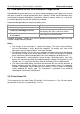
MI 3121H Smartec 2,5 kV Insulation / Continuity Insulation resistance IL IM IM IL +OUT -OUT Ut IA +OUT -OUT Ut A IA IL GUARD A Figure 5.10: Connection of GUARD terminal to measured object where: Ut ........ Test voltage IL ......... Leakage current (resulted by surface dirt and moisture) IM ........ Material current (resulted by material conditions) IA ......... A-meter current Result without using GUARD terminal: RINS = Ut / IA = Ut / (IM + IL) …incorrect result.
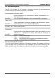
MI 3121H Smartec 2,5 kV Insulation / Continuity Continuity 5.2 Resistance of earth connection and equipotential bonding The resistance measurement is performed in order to assure that the protective measures against electric shock through earth bond connections are effective. Two sub-functions are available: RLOW - Earth bond resistance measurement according to EN 61557-4 (200 mA), CONT - Continuous resistance measurement performed with 7 mA. See chapter 4.
MI 3121H Smartec 2,5 kV Insulation / Continuity Continuity Resistance to earth connection and equipotential bonding measurement procedure Select continuity function (RLOW or CONT) using the BACK / NEXT keys of function selector. Set sub-function to RLOW. Enable and set limit (optional). Connect test lead to the top of the instrument. Compensate the test leads resistance (if necessary, see section 5.2.3). Disconnect from mains supply and discharge installation to be tested.
MI 3121H Smartec 2,5 kV Insulation / Continuity Continuity y z x R S T Test circuit for CONT resistance measurement Figure 5.14: 2-wire test lead application Continuous resistance measurement procedure Select continuity function RLOW or CONT using the BACK / NEXT keys of function selector. Set sub-function CONT. Enable and set the limit (optional). Connect test lead to the instrument. Compensate test leads resistance (if necessary, see section 5.2.3).
MI 3121H Smartec 2,5 kV Insulation / Continuity Continuity 5.2.3 Compensation of test leads resistance This chapter describes how to compensate for test leads resistance in both continuity functions (RLOW and CONT). Compensation is required to eliminate the influence of test leads resistance and the internal resistances of the instrument on the measured resistance. The lead compensation is therefore a very important feature to obtain correct result.
MI 3121H Smartec 2,5 kV Insulation / Continuity Voltage and Frequency 5.3 Voltage and frequency In the VOLT menu the measured voltage and frequency are displayed. See 4.1 Function selection for instructions on key functionality, Figure 5.17: Voltage and frequency display Circuits for voltage measurement L1 L2 L3 N PE N Ro PE L RE Figure 5.
MI 3121H Smartec 2,5 kV Insulation / Continuity Voltage and Frequency Voltage measurement procedure Select the VOLT function. Connect test lead to the instrument. Connect test leads to the tested object (see Figure 5.18). Store voltage measurement result (optional). Measurement starts immediately after selection of VOLT function. Figure 5.19: Example of voltage measurement Displayed results: Voltage between test terminals – value, Voltage between test terminals – analog presentation, Frequency.
MI 3121H Smartec 2,5 kV Insulation / Continuity Memory organization 6 Data handling 6.1 Memory organization Measurement results together with all relevant parameters can be stored in the instrument’s memory. 6.2 Data structure The instrument’s memory place is divided into 2 levels each containing 199 locations. The number of measurements that can be stored into one location is not limited. The data structure describes the identity of the measurement (which object, location).
MI 3121H Smartec 2,5 kV Insulation / Continuity Storing test results 6.3 Storing test results After the completion of a test, the results and parameters are ready for storing (MEM is displayed with result). By pressing the MEM key, the user can store the results. Keys in save test menu - data structure field: Selects the location element (Object / Location) Selects number of selected location element (1 to 199) Saves test results to the selected location and returns to the measuring menu.
MI 3121H Smartec 2,5 kV Insulation / Continuity Clear / Recall 6.5 Clear / recall options Press the MEM key in a main function menu for few seconds to activate possibility for clearing or recalling results. Figure 6.3: Entering menu for recall / clear options on stored results Keys in recall / clear memory menu: UP DOWN TEST Opens menu to clear result at currently selected location. Opens menu to clear all results. Confirms selected clear option (CLR All, see 6.5.1; CLR, see 6.5.
MI 3121H Smartec 2,5 kV Insulation / Continuity Clear / Recall Figure 6.5: Clearing memory in progress 6.5.2 Clearing individual results at selected location After selection of CLEAR result, the instrument will display the following: Figure 6.6: Clear measurements menu Keys in clearing individual results menu (data structure field selected): TAB UP / DOWN TEST Selects the location element (Object / Location). Selects number of selected location element.
MI 3121H Smartec 2,5 kV Insulation / Continuity Communication 6.6 Communication Stored results can be transferred to a PC. A special communication program on the PC automatically identifies the instrument and enables data transfer between the instrument and the PC. There are two communication interfaces available on the instrument: USB or RS 232. The instrument automatically selects the communication mode according to detected interface. USB interface has priority. Figure 6.
MI 3121H Smartec 2,5 kV Insulation / Continuity Maintenance 7 Maintenance Unauthorized persons are not allowed to open the Smartec 2,5 kV Insulation / Continuity instrument. There are no user replaceable components inside the instrument, except the fuse and battery under rear cover. 7.1 Fuse replacement There is a fuse under back cover of the Smartec 2,5 kV Insulation / Continuity instrument. F1 M 0.
MI 3121H Smartec 2,5 kV Insulation / Continuity Technical specifications 8 Technical specifications 8.1 Insulation resistance Insulation resistance (nominal voltages 100 VDC and 250 VDC) Measuring range according to EN61557 is 0.15 MΩ ÷ 999.9 MΩ. Accuracy Measuring range (MΩ) Resolution (MΩ) 0.01 0.00 ÷ 19.99 ±(5 % of reading + 3 digits) 0.1 20.0 ÷ 199.
MI 3121H Smartec 2,5 kV Insulation / Continuity Technical specifications 8.2 Continuity 8.2.1 Resistance RLOW Measuring range according to EN61557 is 0.16 Ω ÷ 1999 Ω. Accuracy Measuring range R (Ω) Resolution (Ω) 0.01 0.00 ÷ 19.99 ±(3 % of reading + 3 digits) 0.1 20.0 ÷ 199.9 ±(5 % of reading) 1 200 ÷ 1999 ±(10 % of reading) Open-circuit voltage.......................... 6.5 VDC ÷ 9 VDC Measuring current............................. min. 200 mA into load resistance of 2 Ω Test lead compensation...........
MI 3121H Smartec 2,5 kV Insulation / Continuity 8.4 Technical specifications General data Power supply voltage........................ 9 VDC (6×1.5 V battery or accu, size AA) Operation .......................................... typical 13 h Charger socket input voltage ............ 12 V ± 10 % Charger socket input current............. 400 mA max Battery charging current.................... 250 mA (internally regulated) Overvoltage category........................
MI 3121H Smartec 2,5 kV Insulation / Continuity Accessory for specific measurements 9 Appendix A - Accessories for specific measurements The table below presents standard and optional accessories required for specific measurement. The accessories marked as optional may also be standard ones in some sets. Please see attached list of standard accessories for your set or contact your distributor for further information. Function Insulation resistance INS Continuity, 200 mA RLOW Continuity.
MI 3121H Smartec 2,5 kV Insulation / Continuity 42 Accessory for specific measurements
MI 3121H Smartec 2,5 kV Insulation / Continuity 43 Accessory for specific measurements
MI 3121H Smartec 2,5 kV Insulation / Continuity 44 Accessory for specific measurements