
Instruction manual


Please unfold page 3. Then you can always see the operating
elements and connections described.
Contents
1 Operating Elements and Connections . . . . . . . . . . . . . . . . 12
2 Safety Notes . . . . . . . . . . . . . . . . . . . . . . . . . . . . . . . . . . . 13
3 Applications . . . . . . . . . . . . . . . . . . . . . . . . . . . . . . . . . . . . 13
4 Setting into Operation . . . . . . . . . . . . . . . . . . . . . . . . . . . . 14
5 Carrying out Measurements . . . . . . . . . . . . . . . . . . . . . . . 14
5.1 Voltage measurement . . . . . . . . . . . . . . . . . . . . . . . . . . . . 15
5.2 DC current measurement . . . . . . . . . . . . . . . . . . . . . . . . . 15
5.3 Resistance measurement . . . . . . . . . . . . . . . . . . . . . . . . . 16
5.4 Continuity check . . . . . . . . . . . . . . . . . . . . . . . . . . . . . . . . .16
5.5 Decibel . . . . . . . . . . . . . . . . . . . . . . . . . . . . . . . . . . . . . . . . 17
5.6 Battery test . . . . . . . . . . . . . . . . . . . . . . . . . . . . . . . . . . . . . 17
5.7 Transistor test (with model MT-300 only) . . . . . . . . . . . . . . 17
6 Replacing of Batteries or Fuse . . . . . . . . . . . . . . . . . . . . . 18
7 Specifications . . . . . . . . . . . . . . . . . . . . . . . . . . . . . . . . . . . 19
1 Operating Elements and Connections
1 Range switch
2 Button “0Ω CAL. SW” for bridging the jacks “ COM” (4) and
“V.Ω.A” (10) for the 0 Ω calibration (with model MT-300 only):
while 0 Ω calibrating, keep this button pressed, by this the
short-circuiting of the test lead tips is not necessary which is
otherwise usual
3 Plug-in connections for testing transistors, with LEDs situated
above to indicate the transistor type (with model MT-300 only)
4 Jack “ COM” for the black test lead (negative pole)
5 Mirror scale to eliminate parallax errors while reading the
measuring value
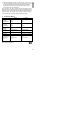
6 Table with dB values which must be added to the reading value
during the dB measurement unless the lowest AC voltage
range has been selected
GB
12