
User Manual

7
71503175-0-000
EN
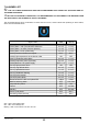
refrigerating circuit of the appliance is
shown on the identication plate (g. 12).
The GWP (Global Warming Potential) of
HFC R452A gas is 2141.
The CO2 equivalent data is present on the
serial number plate (g. 12).
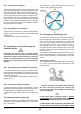
• According to Regulation (EC) 1272/2008,
R452A gas is a non-ammable and
non-toxic gas
.
2 PREFACE
Thank you for choosing one of our products.
This device (machine) was designed by our techni-
cians and manufactured in our establishments having
an experience of decades and taking care to meet the
highest quality standards. Our ISO 9001 certied qual-
ity system allows you to control all business processes
for continuous improvement of the quality and safety
of our products.
Immediately read this brochure which will help you
familiarising with the machine which, if installed and
used correctly according to the instructions, shall not
present risk situations or danger for the user.
It is important to always observe the contained instruc-
tions and that in no way the user accesses inside the
compressor - condenser compartment and to tamper
with the control and safety devices.
We recommend carefully reading our warnings for a
TABLE OF CONTENTS
1 WARNINGS .................................................................. 5
2.1 Machine operation ....................................................7
2.2 Warranty ...................................................................8
3 INSTALLATION ............................................................ 8
3.1 Transportation ..........................................................8
3.2 Unpacking and disposal ...........................................8
3.3 Positioning ................................................................8
3.4 Connection to the electrical power supply ................9
4 COMMISSIONING ........................................................ 9
4.1 Ice cubes adjustment ..............................................10
4.2 Water hardness indication ........................................10
4.3 Bin Probe Adjustment (optional) ...............................10
5 CLEANING AND MAINTENANCE.............................. 10
5.1 Operations to be performed by the user ..................10
5.1.1 External body cleaning ...............................................10
5.1.2 Cleaning the air lters ................................................11
5.1.2 Cleaning the ice container ..........................................11
5.2 Operations to be performed by the enabled installer ...11
5.2.1 Cleaning the air condenser (if present) ...................... 11
5.2.2 Cleaning the water inlet lter ......................................11
5.3 Ozone activation (optional) .......................................11
5.4 Cleaning and sanitising cycle ...................................11
6 MALFUNCTION .......................................................... 12
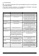
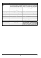
7 ALARMS LIST ............................................................ 13
7.1 Troubleshooting ........................................................14
correct and better use of your ice maker so that it op-
erates for a long period of time without causing prob-
lems. If you need to contact the manufacturer or a des-
ignated representative, always quote the model and
serial number of your appliance (g.12).
2.1 Machine operation
Ice cubes are formed in a special copper hive-
shaped vertical evaporator. A recirculation pump
makes a continuous flow of water run over the front
grid and, gradually, part of the water turns into ice
on the inner walls of the small cells, forming cubes
that reach the expected size in height. The size
of the block of ice depends on the set water level
(which indicates how much water is transformed
into ice); the sensor consists of two metal blades
powered by a low-voltage circuit, isolated from
one another and immersed in the water in the
basin (Fig. 13).
As the ice forms, the water level decreases, until it no
longer closes the electronic circuit, which simultane-
ously causes the following:
• it sends the hot gas to the evaporator by opening
a solenoid valve causing the block of ice to gradually
detach.
• the action of an electromechanical pushing device
which helps to detach the blocks of ice from the evap-
orator.
• opening the water drainage valve to eliminate any
residual impurities.
Once the block of ice has detached, it moves towards
the outside of the front deector and falls into the con-
tainer by gravity. The central deector as it turns rst
forwards and then backwards, opens and closes the
contacts of a micro magnetic switch, connected to an
electronic board, which resets the normal ice produc-
tion cycle. When the container is full, the last block of
ice keeps the deector open and so the microswitch
contacts stay open. In these conditions, the electronic
board stops the machine after 30 seconds. Remov-
ing the ice from the storage bin allows the deector
to return to its normal position and the ice maker to
restart. The time for the complete cycle may vary from
about 15’ to 30’ depending on the water and ambient
temperature.
If the machine stops due to irregular operation, the illu-
minated area of the capacitative button lights up with a
particular sequence of colours indicating the alarm in
progress.Never shut o the water when the machine is
operating and do not obstruct the air intakes.
When restarting a cold cycle or switching to standby,
the machine will perform a defrost cycle to prevent ice
from accumulating on the evaporator.
i Note: In the case of production control with a sen-
sor in the bin (optional), after collecting the ice, remove
any ice residues from the control bulb so that produc-
tion can resume faster.