
Tus neeg siv phau ntawv
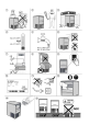
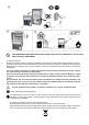
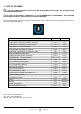
Table Of Contents

pag. 8
71504165-0-005
EN
refrigerating circuit of the appliance is
shown on the identication plate (g. 10).
The GWP (Global Warming Potential) of
the R134a HFC gas is 1430.
The CO2 equivalent data is present on the
serial number plate (g. 10).
• According to Regulation (EC) 1272/2008,
R134a gas is a non-ammable and non-tox
-
ic gas
.
2 PREFACE
Thank you for choosing one of our products.
This device (machine) was designed by our techni-
cians and manufactured in our establishments having
an experience of decades and taking care to meet the
highest quality standards. Our ISO 9001 certied qual-
ity system allows you to control all business processes
for continuous improvement of the quality and safety
of our products.
Immediately read this brochure which will help you
familiarising with the machine which, if installed and
used correctly according to the instructions, shall not
present risk situations or danger for the user.
It is important to always observe the contained instruc-
tions and that in no way the user accesses inside the
compressor - condenser compartment and to tamper
with the control and safety devices.
We recommend carefully reading our warnings for a
TABLE OF CONTENTS
1 WARNINGS ........................................................................ 6
2.1 Machine operation ..........................................................8
2.2 Warranty .........................................................................9
3 INSTALLATION .................................................................. 9
3.1 Transportation ................................................................9
3.2 Unpacking and disposal .................................................9
3.3 Positioning ......................................................................9
3.4 Connection to the electrical power supply .....................10
4 COMMISSIONING ........................................................... 10
4.1 Ice cubes adjustment ....................................................10
4.2 Bin probe adjustment .....................................................11
5 CLEANING AND MAINTENANCE ...................................11
5.1 Operations to be performed by the user ......................11
5.1.1 External body cleaning .................................................... 11
5.1.2 Cleaning the ice container ................................................ 11
5.2 Operations to be performed by the enabled installer ...11
5.2.1 Cleaning the air condenser (if present) .......................... 11
5.2.2 Cleaning the water inlet lter ........................................... 11
5.3 Ozone activation (optional) ............................................11
5.4 Cleaning and sanitising cycle ........................................11
6 MALFUNCTION ............................................................... 12
7 LIST OF ALARMS ........................................................... 13
7.1 Troubleshooting ..............................................................14
correct and better use of your ice maker so that it op-
erates for a long period of time without causing prob-
lems. If you need to contact the manufacturer or a des-
ignated representative, always quote the model and
serial number of our device (g.10).
2.1 Machine operation
Ice cube makers can be easily adapted to the
furnishings of each room.
- They mainly consist of:
a) A refrigerating circuit that provides the cooling
capacity to obtain the ice and the hot gas to detach the
ice at the end of the cycle.
b) An area called evaporator, consisting of cooled
metal cups, in which the ice if formed
c) a pump and a sprayer to recirculate the water, which
is then turned into ice, by collecting it from a bowl and
spraying it evenly on the cooled cups of the evaporator,
thus ensuring the formation of ice.
d) nally a bin that contains the ice produced
- the production cycle stops either because the probe
in the bin detects that the bin is full or because the user
switches o the machine.
- The formation of ice cubes takes place inside cooled
metal cups located in the top part of the machine called
evaporator; during the ice formation phase, these cups
are always sprayed with water by a sprayer placed
below them; the sprayer is fed by a pump that collects
a certain amount of water from the underlying bowl,
and recirculates it, so it can gradually turn into ice.
- When the ice cubes have reached the expected
size, the evaporator probe detects the right conditions
and, by means of the electronic board, it activates
the opening of the hot gas valve which heats the
evaporator, and simultaneously opens the water inlet
valve, lling the bowl and also helping the ice cubes
detach from the evaporator. During this phase, the
pump remains still in order not to ruin the ice being
detached.
- Once detached, the cubes slide on an inclined
grid located inside the tray and are conveyed to the
underlying bin.
- after a certain time dened by the board, the hot
gas valve closes again and the ice formation phase
restarts; the time for a complete cycle may vary from
about 15’ to about 35’ depending on the water and
ambient temperatures.
- The amount of ice in the bin is controlled by the
electronic probe xed on a wall of the bin; when the
cubes reach the level of the bulb the machine stops
completely. After removal of the ice, allowing the bulb
to be released from contact with the cubes, the ice
maker will resume its normal production.
i Note: After collecting the ice, remove any residues
from the control bulb so that production can resume
faster.