S H A R K SHARK MULTI-PARAMETER CONTROLLER & ANALYZER USER’S MANUAL Rev 3 AquaMetrix Inc. 1245 Maple Hill Ct., Unit 7 Newmarket, ON Canada, L3Y 9E8 Tel: (800) 742-1413 (905) 954-0841 Fax: (905) 954-0415 www.aquametrix.
MULTI-PARAMETER CONTROLLER & ANALYZER USER’S MANUAL S H A R K Table of Contents Subject Page No.
MULTI-PARAMETER CONTROLLER & ANALYZER USER’S MANUAL S H A R K Introduction The SHARK multi-parameter controller is a microprocessor based controller capable of measuring one of the following parameters, pH, ORP, conductivity or flow. When shipped from the factory, the SHARK is not set to measure any one parameter. When the SHARK is powered up for the first time, it will display the meter selection screen where the meter type must be selected. (refer to section 4.
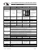
MULTI-PARAMETER CONTROLLER & ANALYZER USER’S MANUAL S H A R K Section I - Specifications Display Power Requirements Measuring Range pH ORP Conductivity Front Panel: 4 x 7 segment 1/2” LED display, 1 LED indicator 0n-line,7 LED Bar Graph Inside Panel: 2 x 16 alpha-numeric LCD display 120Vac (±10%) 50/60Hz (less than 12VA) or 240Vac (±10%) 50/60Hz (less than 12VA) pH: 0.01 to 14.
MULTI-PARAMETER CONTROLLER & ANALYZER USER’S MANUAL S H A R K Section 2 - Installation 2.1 Unpacking Save the shipping carton and packing material in case the instrument needs to be stored or returned. Inspect the instrument and packing material for shipping damage and report any problems immediately. 2.2 Location Locate the controller/analyzer close to the sensor. The list below gives typical maximum distances for various sensors. Refer to the sensor specifications for exact information.
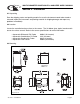
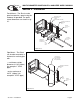
MULTI-PARAMETER CONTROLLER & ANALYZER USER’S MANUAL S H A R K Section 2 - Installation Panel Mount – The Shark can be panel mounted to a panel using the hardware kit provided. The panel cutout dimensions are shown in fig. 2.1. Figure 2.2 Panel Mount EXTERNAL PANEL GASKET QTY.1 PANEL (CUSTOMER SUPPLIED) UNIVERSAL MOUNTING BRACKET QTY.1 SCREW 10-24 X 1/2" QTY.4 SCREW 1/4-20 X 6" QTY.4 UNIVERSAL MOUNTING CLAMP QTY.2 NUT 1/4-20 QTY.
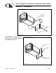
MULTI-PARAMETER CONTROLLER & ANALYZER USER’S MANUAL S H A R K Section 2 - Installation Figure 2.4 Horizontal Pipe Mount MIN. PIPE DIA. 1" PIPE (NOMINAL) MAX. PIPE DIA. 2" PIPE (NOMINAL) NUT 10-24 QTY.4 SCREW 10-24 X 3-1/2" QTY.4 UNIVERSAL MOUNTING BRACKET QTY.1 Dwg# N105-100 Surface Mount – The Shark can be surface mounted using the hardware kit provided with the unit. Figure 2.5 Surface Mount UNIVERSAL MOUNTING BRACKET QTY.1 SCREW 10-24 X 1/2" QTY.4 HOLES Ø1/4" FOR MOUNTING SCREWS QTY.
MULTI-PARAMETER CONTROLLER & ANALYZER USER’S MANUAL S H A R K Section 3 - Electrical Connections and Setup 3.1 Conduit Connections The Shark has four 1/2” conduit holes, 2 on each side of the enclosure as shown on fig. 2.1. The unit is shipped with these holes plugged with liquid tight conduit seals. These must be left in unused holes to maintain the NEMA 4X integrity. Use approved conduit hubs to connect the conduit, connect these to the conduit before connecting to the enclosure.
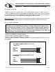
MULTI-PARAMETER CONTROLLER & ANALYZER USER’S MANUAL S H A R K Section 3 - Electrical Connections and Setup 3.3 pH and ORP Differential Probe connections and setup The drawing shows the connections for the Aquametrix Differential (5 wire) probe. The cable should be run in a conduit separate from AC power wires, and via a separate conduit hole. Note: Leave 4” to 6” slack for all wires connected to the terminals of P6.
MULTI-PARAMETER CONTROLLER & ANALYZER USER’S MANUAL S H A R K Section 3 - Electrical Connections and Setup 3.4 pH or ORP Combination Probe connections and setup The drawing shows the connections for the Aquametrix Combination probe. The cable should be run in a conduit separate from AC power wires, and via a separate conduit hole. The cable length should not exceed 10 feet (3 meters). Fig. 3.
MULTI-PARAMETER CONTROLLER & ANALYZER USER’S MANUAL S H A R K Section 3 - Electrical Connections and Setup 3.5 Conductivity Cell (Contacting style) connections and setup The drawing shows the connections for the Aquametrix Conductivity Cells (Contacting style). The cable should be run in a conduit seperate from the AC power wires, and via a seperate conduit hole. The cell cable length should not exceed 300ft. (91 meters). Note: Leave 4” to 6” slack for all wires connected to the terminals of P6.
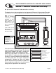
MULTI-PARAMETER CONTROLLER & ANALYZER USER’S MANUAL S H A R K Section 3 - Electrical Connections and Setup 3.6 Paddle Wheel Flow Sensor connections and setup The drawing shows the connnections for a typical paddle wheel flow sensor. The cable to the sensor should not exceed 2000’ (600 meters). The Shark controller also supports the use of an external “flow switch”. When the flow switch input is grounded, either through a dry contact or solid state input, the flow display will be held at zero.
MULTI-PARAMETER CONTROLLER & ANALYZER USER’S MANUAL S H A R K Section 3 - Electrical Connections and Setup 3.7 Relay connections The Shark controller has three internal relays. Relays A and B are for control, the Alarm Relay can be configured for alarm functions or as an additional control relay. The connections to the relays are shown in the drawing. Note that the AC power is internally connected to the relay terminal plug P4. This is used to provide 120V or 240V AC power for the relay contacts.
MULTI-PARAMETER CONTROLLER & ANALYZER USER’S MANUAL S H A R K Section 3 - Electrical Connections and Setup 3.8 RELAY A and B Setup (LCD MENU SECTIONS - pH: 4.18 & 4.19, ORP: 5.17 & 5.18, Conductivity: 6.18 & 6.19, Flow: 7.15 & 7.16) Relay A & Relay B on the SHARK are SPDT dry contact relays. They are configurable to operate in response to rising or falling process values. Each relay has independently adjustable on and off setpoints, cycle times, and fail-safe options.
MULTI-PARAMETER CONTROLLER & ANALYZER USER’S MANUAL S H A R K Section 3 - Electrical Connections and Setup 3.9 ALARM RELAY Setup (LCD MENU SECTIONS - pH: 4.20, ORP: 5.19, Conductivity: 6.20, Flow: 7.17) The third relay (Relay C) is used as an alarm relay. The alarm relay on the SHARK is a SPDT dry contact relay. This relay will respond to both a rising and falling process. The alarm relay will act as a low alarm (falling process) and a high alarm (rising process).
MULTI-PARAMETER CONTROLLER & ANALYZER USER’S MANUAL S H A R K Section 3 - Electrical Connections and Setup 3.10 MANUAL TEST MODE (LCD MENU SECTIONS - pH: 4.4, ORP: 5.3, Conductivity: 6.4, Flow: 7.2) Once the relays are configured, the setup can be tested using Manual Test Mode to simulate process changes. MANUAL TEST MODE is used to simulate a process reading in order to verify the correct response of the outputs.
MULTI-PARAMETER CONTROLLER & ANALYZER USER’S MANUAL S H A R K Section 3 - Electrical Connections and Setup 3.12 4-20 mA Isolated Outputs Channel 1 and Channel 2 Figure 3.7 Connections for the 4-20mA outputs (LCD MENU SECTIONS - pH: 4.21 & 4.22, ORP: 5.20 & 5.21, 21 22 23 24 25 26 27 28 29 30 31 67 66 65 64 63 62 61 60 59 58 57 56 55 54 53 52 51 Conductivity: 6.21 & 6.22, Flow: 7.18 & 7.19) The Shark Controller has two 4 to 20mA outputs, electrically isolated from each other and ground.
MULTI-PARAMETER CONTROLLER & ANALYZER USER’S MANUAL S H A R K Section 3 - Electrical Connections and Setup 3.13 Service SHARK SERVICE TO BE PERFORMED BY QUALIFIED PERSONNEL ONLY. 3.14 Fuse Replacement WARNING: DISCONNECT LINE POWER TO THE UNIT TO AVOID THE POSSIBILITY OF ELECTRICAL SHOCK. Figure 3.8 Fuse Location 2. Open the front panel by rotating the quarter-turn fasteners, using a flat blade screwdriver, to expose the relay board. 3.
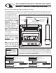
MULTI-PARAMETER CONTROLLER & ANALYZER USER’S MANUAL S H A R K Section 4 - Using the SHARK in pH Mode 1/4" TURN SCREWS 4 DIGIT, 7 SEGMENT LED DISPLAY RUN LED (GREEN) DISPLAYS PROCESS VALUE IN RUN MODE. DISPLAYS CALIBRATION DATA IN CALIBRATION MODE. LED WILL BE ILLUMINATED WHEN SHARK IS IN THE RUN MODE. WILL BE OFF WHEN SHARK IS IN THE MENU MODE. OVERFEED LED (RED) LED WILL FLASH WHEN THE OVERFEED TIMER IS ACTIVATED.
MULTI-PARAMETER CONTROLLER & ANALYZER USER’S MANUAL S H A R K pH - Menu Overview 4.0 RUN MODE 7.15pH 25.0C DOWN CALIBRATION DOWN MANUAL CALIBRATE pH PROBE SEC. 4.1 MANUAL CAL PH UTILITIES DOWN DOWN AUTO CALIBRATE pH PROBE SEC. 4.2 AUTO CAL PH SETUP DOWN DOWN TEMP CALIBRATION DIAGNOSTICS DOWN DOWN CALIBRATE TEMP. SENSOR IN pH PROBE SEC. 4.3 EXIT OUTPUTS DOWN DOWN EXIT DOWN PROBE SELECT DOWN TEMP UNIT SELECT TYPE OF pH PROBE SEC. 4.8 SELECT DEG C OR DEG F SEC 4.
MULTI-PARAMETER CONTROLLER & ANALYZER USER’S MANUAL S H A R K pH - Calibration Menu - Manual Calibrate 4.1 7.15pH 25.0C RUN MODE DOWN CALIBRATION MANUAL CAL PH Place the probe in the first buffer solution, be sure to clean and rinse the Probe first with D.I. water and then insert it in the 7.00 buffer. IF BUFFER1 READY PRESS 'DOWN' Press DOWN RUNNING MANU CAL BUFFER1 WAIT... MANUAL CAL PH BUFFER1 UP 7.3 5 > DOWN MANUAL CAL PH BUFFER1 7.0 0 > MANUAL CAL PH BUFFER1 7.
MULTI-PARAMETER CONTROLLER & ANALYZER USER’S MANUAL S H A R K pH - Calibration Menu - Auto Calibrate 4.2 7.15pH 25.0C RUN MODE DOWN CALIBRATION MANUAL CAL PH DOWN AUTO CAL PH Place the probe in the first buffer solution, be sure to clean and rinse the Probe first with D.I. water and then insert it in the 7.00 buffer. IF BUFFER1 READY PRESS 'DOWN' DOWN Press RUNNING AUTO CAL BUFFER1 WAIT... The controller will read the pH value, averaging a number of results to get a stable calibration value.
MULTI-PARAMETER CONTROLLER & ANALYZER USER’S MANUAL S H A R K pH - Calibration Menu - Temperature Calibration 4.3 7.15pH 25.0C RUN MODE DOWN CALIBRATION MANUAL CAL PH If the Temperature Compensation Override is set to ON (see section 4.12), the Shark cannot calibrate the temperature sensor. This display will appear to alert the user to the condition. DOWN AUTO CAL PH DOWN TEMP CALIBRATION TEMP CALIBRATION TEMP O/R ON > DOWN The controller displays the current probe temperature.
MULTI-PARAMETER CONTROLLER & ANALYZER USER’S MANUAL S H A R K pH - Utilities Menu - Manual Test Mode 4.4 7.15pH 25.0C Manual Test Mode is used to simulate a process reading in order to verify the correct response of the outputs. When in the Manual Test Mode, the outputs are no longer placed on hold as they are when in the rest of the menu. RUN MODE DOWN CALIBRATION DOWN UTILITIES MANUAL TEST MODE TEST abc 7.00 > 12.
MULTI-PARAMETER CONTROLLER & ANALYZER USER’S MANUAL S H A R K pH - Utilities Menu - Relay Override 4.5 Relay Override is used to manually override the state of the relays, the user is able to set the operating mode of the relay as AUTO/ON/OFF (the default and run mode state are AUTO). This feature can be used to turn the relays ON or OFF to manually correct the process, or to shut down an ancillary device to perform maintenance.
MULTI-PARAMETER CONTROLLER & ANALYZER USER’S MANUAL S H A R K pH - Utilities Menu - Relay Override 4.5 FROM RELAY B OVERRIDE MENU If you wish to Override Relay C, Press the key once which will move the RELAY OVERRIDE RELAY C AUTO Use the UP or DOWN key to change the Override state from AUTO - controlled by process settings ON - relay forced on OFF- relay forced off If you wish to accept the The relay will react Override setting, immediately.
MULTI-PARAMETER CONTROLLER & ANALYZER USER’S MANUAL S H A R K pH - Utilities Menu - Meter Selection 4.6 7.15pH 25.0C RUN MODE The Meter Selection menu is used to select the meter type that the controller is configured for, either pH, ORP, Conductivity or FLow. Once selected, the controller will initialize itself for the selected meter's functionality and move to run mode.
MULTI-PARAMETER CONTROLLER & ANALYZER USER’S MANUAL S H A R K pH - Utilities Menu - Overfeed Timer Reset 4.7 7.15pH 25.0C If the control relay overfeed timer has been enabled, the relay will “time out” after the specified overfeed time. When the relay times out, it must be manually reset. The time out will be signaled by the time out LED flashing on the front panel.
MULTI-PARAMETER CONTROLLER & ANALYZER USER’S MANUAL S H A R K pH - Setup Menu - Probe Select 4.8 7.15pH 25.0C RUN MODE DOWN CALIBRATION DOWN PROBE SELECT will allow the user to select whether the probe is a 2 or 4 wire combination probe, or a 5 wire differential probe. UTILITIES DOWN SETUP PROBE SELECT PROBE SELECT DIFFERENTIAL > DOWN Use the UP or DOWN keys to scroll through the probe types available.
MULTI-PARAMETER CONTROLLER & ANALYZER USER’S MANUAL S H A R K pH - Setup Menu -Temp Unit 4.9 7.15pH 25.0C RUN MODE TEMP UNIT allows the user to select either Degrees Centigrade or Fahrenheit units for display DOWN CALIBRATION DOWN UTILITIES DOWN SETUP PROBE SELECT DOWN TEMP UNIT TEMP UNIT DEGREE C > TEMP UNIT DEGREE C UP Press the key once which will move the cursor over the unit type, C or F.
MULTI-PARAMETER CONTROLLER & ANALYZER USER’S MANUAL S H A R K pH - Setup Menu - Temp. Sensor 4.10 7.15pH 25.0C RUN MODE TEMP SENSOR allows the user to select the type of temperature sensor used the in the probe. DOWN CALIBRATION The factory default for pH is a 300 Ω NTC Thermistor. The user can also select a 3000 Ω NTC Thermistor or a 1000 RTD.
MULTI-PARAMETER CONTROLLER & ANALYZER USER’S MANUAL S H A R K pH - Setup Menu - Auto Return 4.11 7.15pH 25.0C RUN MODE AUTO RETURN is used to select what conditions will cause the controller to time-out of the operations menu, or reset the relay override function. DOWN CALIBRATION DOWN UTILITIES DOWN MENU ON will cause the controller to exit the menu and revert back to the online run mode after 10 minutes with no buttons pressed.
MULTI-PARAMETER CONTROLLER & ANALYZER USER’S MANUAL S H A R K pH - Setup Menu - T.Comp Override 4.12 7.15pH 25.0C RUN MODE Temperature Compensation Override is used to manually set the actual probe or process temperature. This is useful if the probe does not have a temperature sensor or if the process temperature is constant. When the override is enabled, the controller will use the selected temperature when performing temperature compensation calculations.
MULTI-PARAMETER CONTROLLER & ANALYZER USER’S MANUAL S H A R K pH - Setup Menu - Display Damping 4.13 7.15pH 25.0C RUN MODE DOWN CALIBRATION DOWN UTILITIES The Display Damping menu allows the user to adjust the rate at which the display and all outputs are updated. This allows the user to dampen out unstable process readings. The damping can be set from 0 seconds to 10 seconds. (default value is 0 sec.) DOWN SETUP PROBE SELECTION DOWN TEMP UNIT DOWN TEMP SENSOR DOWN AUTO RETURN DOWN T.
MULTI-PARAMETER CONTROLLER & ANALYZER USER’S MANUAL S H A R K pH - Setup Menu - Bar Graph O/R 4.14 7.15pH 25.0C RUN MODE The BAR GRAPH O/R menu allows the user control over the resolution of the bar graph on the front panel of the Shark. The factory default for this function is "OFF" which means the 3 green LEDS are set to operate between the ON set points of Relay A and B. This may not always be acceptable, and this function allows the user to override these settings.
MULTI-PARAMETER CONTROLLER & ANALYZER USER’S MANUAL S H A R K pH - Diagnostics Menu - Firmware Rev 4.15 7.15pH 25.0C RUN MODE DOWN CALIBRATION The FIRMWARE REV menu allows the user to see what revision of the firmware is currently installed in the controller. This is a Read Only menu item. DOWN UTILITIES DOWN SETUP DOWN DIAGNOSTICS FIRMWARE REV. FIRMWARE REV. 1.15 DOWN pH - Diagnostics Menu - Firmware Rev 4.
MULTI-PARAMETER CONTROLLER & ANALYZER USER’S MANUAL S H A R K pH - Diagnostics Menu - Calibration Data 4.16 7.15pH 25.0C RUN MODE The Calibration Data menu is a series of read only screens which allow the user to view the data collected during the last calibration. DOWN CALIBRATION DOWN UTILITIES DOWN SETUP DOWN DIAGNOSTICS FIRMWARE REV. DOWN CALIBRATION DATA Press to view the first Calibration Data screen. CALIBRATION DATA MODE 2PT > Press DOWN to view the next Calibration Data screen.
MULTI-PARAMETER CONTROLLER & ANALYZER USER’S MANUAL S H A R K pH - Diagnostics Menu - Sensor Input 4.17 7.15pH 25.0C RUN MODE DOWN CALIBRATION DOWN The Sensor Input Menu allows the user to view real time, uncompensated process data from the probe. This is a Read only menu item. UTILITIES DOWN SETUP DOWN DIAGNOSTICS FIRMWARE REV. DOWN CALIBRATION DATA DOWN SENSOR INPUT Press to view the Sensor Input data.
MULTI-PARAMETER CONTROLLER & ANALYZER USER’S MANUAL S H A R K pH - Outputs Menu - Relay A 4.18 7.15pH 25.
MULTI-PARAMETER CONTROLLER & ANALYZER USER’S MANUAL S H A R K pH - Outputs Menu - Relay A 4.18 The relay can be set to CYCLE when the process is between the RELAY ON setting and the RELAY OFF setting. This is meant to help eliminate overshoot. The CYCLE ON time is the amount of time in seconds that the relay will be on. The value can be set between 0 and 600 seconds. The default ON time is 5 seconds.
MULTI-PARAMETER CONTROLLER & ANALYZER USER’S MANUAL S H A R K pH - Outputs Menu - Relay B 4.19 7.15pH 25.
MULTI-PARAMETER CONTROLLER & ANALYZER USER’S MANUAL S H A R K pH - Outputs Menu - Relay B 4.19 The relay can be set to CYCLE when the process is between the RELAY ON setting and the RELAY OFF setting. This is meant to help eliminate overshoot. The CYCLE ON time is the amount of time in seconds that the relay will be on. The value can be set between 0 and 600 seconds. The default ON time is 5 seconds.
MULTI-PARAMETER CONTROLLER & ANALYZER USER’S MANUAL S H A R K pH - Outputs Menu - Alarm Relay 4.20 7.15pH 25.0C RUN MODE The ALARM RELAY will respond to both a rising and falling process. The ALARM RELAY will act as a low alarm (falling process) and a high alarm (rising process). Both relay bands will have independently adjustable on and off set-points. If a low alarm set-point is set at a value 3.00pH for example, the off setpoint must be set higher.
MULTI-PARAMETER CONTROLLER & ANALYZER USER’S MANUAL S H A R K pH - Outputs Menu - Alarm Relay 4.20 FROM HIGH ON The HIGH OFF set- point is the value that the must reach in order to de-energize the alarm relay after it has increased over and tripped the HIGH ON setpoint. This value must be lower than the HIGH ON Set-point. ALARM RELAY HIGH OFF 9.
MULTI-PARAMETER CONTROLLER & ANALYZER USER’S MANUAL S H A R K pH - Outputs Menu - 4-20mA CH1 Output 4.21 RUN MODE 7.15pH 25.0C The Controller has 2 4-20mA outputs, electrically isolated from each other and ground. Either output can source current into a maximum of 800 ohms. See Section 3.12 for wiring diagram. Channel 1 (the primary output) is located on the flip out door, terminal plug P6.
MULTI-PARAMETER CONTROLLER & ANALYZER USER’S MANUAL S H A R K pH - Outputs Menu - 4-20mA CH2 Output 4.22 7.15pH 25.0C RUN MODE The Controller has 2 4-20mA outputs, electrically isolated from each other and ground. Either output can source current into a maximum of 800 ohms. Channel 2 can be selected to track the process or temperature. Channel 2 has fully independent and fully adjustable 4 & 20 mA output adjustments. This will enable the operator to span the output over the desired range.
MULTI-PARAMETER CONTROLLER & ANALYZER USER’S MANUAL S H A R K pH - LED Display Menu - pH Auto Calibrate 4.23 RUN Press the ENTER key to select Manual Calibration CAL MANUAL CALIBRATE This menu allows the user to manually calibrate the probe, the user enters the known buffer values AUTO CALIBRATE Auto Calibrate will automatically detect the buffers used to calibrate, and set the display to the appropriate settings.
MULTI-PARAMETER CONTROLLER & ANALYZER USER’S MANUAL S H A R K pH - LED Display Menu - pH Manual Calibrate 4.24 MANUAL CALIBRATE TO AUTO CALIBRATE The Controller will display bUF1, prompting the user to place the probe in the first buffer solution. ENTER Be sure to clean and rinse the Probe first with D.I. water and then insert it in the 7.00 buffer. Press the ENTER key. The controller will flash "bUF1" for about 10 seconds while is reads the buffer.
MULTI-PARAMETER CONTROLLER & ANALYZER USER’S MANUAL S H A R K Section 5 - Using the SHARK in ORP Mode 1/4" TURN SCREWS 4 DIGIT, 7 SEGMENT LED DISPLAY RUN LED (GREEN) DISPLAYS PROCESS VALUE IN RUN MODE. DISPLAYS CALIBRATION DATA IN CALIBRATION MODE. LED WILL BE ILLUMINATED WHEN SHARK IS IN THE RUN MODE. WILL BE OFF WHEN SHARK IS IN THE MENU MODE. OVERFEED LED (RED) LED WILL FLASH WHEN THE OVERFEED TIMER IS ACTIVATED.
MULTI-PARAMETER CONTROLLER & ANALYZER USER’S MANUAL S H A R K ORP - Menu Overview 5.0 RUN MODE 500mV 25.0C DOWN CALIBRATION DOWN MANUAL CAL ORP UTILITIES DOWN DOWN TEMP CALIBRATION SETUP DOWN DOWN MANUAL CALIBRATE ORP PROBE SEC. 5.1 CALIBRATE TEMP. SENSOR IN ORP PROBE SEC. 5.2 EXIT DIAGNOSTICS DOWN DOWN OUTPUTS DOWN EXIT MANUAL TEST MODE DOWN DOWN PROBE SELECT DOWN TEMP UNIT SELECT TYPE OF ORP PROBE SEC. 5.7 SELECT DEG C OR DEG F SEC 5.8 TEMP SENSOR DOWN AUTO RETURN DOWN T.
MULTI-PARAMETER CONTROLLER & ANALYZER USER’S MANUAL S H A R K ORP - Calibration Menu - Manual Calibrate 5.1 500mV 25.0C RUN MODE DOWN CALIBRATION MANUAL CAL ORP Place the probe in the buffer solution, be sure to clean and rinse the Probe first with D.I. water and then insert it in the mV buffer. IF BUFFER READY PRESS 'DOWN' Press DOWN DOWN The controller will read the mV value, averaging a number of results to get a stable calibration value. RUNNING MANU CAL BUFFER WAIT...
MULTI-PARAMETER CONTROLLER & ANALYZER USER’S MANUAL S H A R K ORP - Calibration Menu - Temp. Calibration 5.2 500mV 25.0C RUN MODE If the Temperature Display Override is set to ON (see section 5.11), the Shark cannot calibrate the temperature sensor. This display will appear to alert the user to the condition. DOWN CALIBRATION MANUAL CAL PH DOWN TEMP CALIBRATION TEMP CALIBRATION TEMP O/R ON > DOWN The controller displays the current probe temperature.
MULTI-PARAMETER CONTROLLER & ANALYZER USER’S MANUAL S H A R K ORP - Utilities Menu - Manual Test Mode 5.3 500mV 25.0C Manual Test Mode is used to simulate a process reading in order to verify the correct response of the outputs. When in the Manual Test Mode, the outputs are no longer placed on hold as they are when in the rest of the menu. RUN MODE DOWN CALIBRATION The range is 0 to +1000mV. DOWN UTILITIES MANUAL TEST MODE TEST abc 500 > 12.
MULTI-PARAMETER CONTROLLER & ANALYZER USER’S MANUAL S H A R K ORP - Utilities Menu - Relay Override 5.4 Relay Override is used to manually override the state of the relays, the user is able to set the operating mode of the relay as AUTO/ON/OFF (the default and run mode state are AUTO). This feature can be used to turn the relays ON or OFF to manually correct the process, or to shut down an ancillary device to perform maintenance.
MULTI-PARAMETER CONTROLLER & ANALYZER USER’S MANUAL S H A R K ORP - Utilities Menu - Relay Override 5.4 FROM RELAY B OVERRIDE MENU RELAY OVERRIDE RELAY C AUTO If you wish to Override Relay C, Press the key once which will move the cursor over to the AUTO/ON/OFF text Use the UP or DOWN key to change the Override state from AUTO - controlled by process settings ON - relay forced on OFF- relay forced off If you wish to accept the The relay will react Override setting, immediately.
MULTI-PARAMETER CONTROLLER & ANALYZER USER’S MANUAL S H A R K ORP - Utilities Menu - Meter Selection 5.5 500mV 25.0C RUN MODE The Meter Selection menu is used to select the meter type that the controller is configured for, either pH, ORP, Conductivity or FLow. Once selected, the controller will initialize itself for the selected meter's functionality and move to run mode.
MULTI-PARAMETER CONTROLLER & ANALYZER USER’S MANUAL S H A R K ORP - Utilities Menu - Overfeed Timer Reset 5.6 500mV 25.0C If the control relay overfeed timer has been enabled, the relay will “time out” after the specified overfeed time. When the relay times out, it must be manually reset. The time out will be signaled by the time out LED flashing on the front panel.
MULTI-PARAMETER CONTROLLER & ANALYZER USER’S MANUAL S H A R K ORP - Setup Menu - Probe Select 5.7 500mV 25.0C RUN MODE DOWN CALIBRATION DOWN PROBE SELECT will allow the user to select whether the probe is a 2 or 4 wire combination probe, or a 5 wire differential probe. UTILITIES DOWN SETUP PROBE SELECT PROBE SELECT DIFFERENTIAL > DOWN Use the UP or DOWN keys to scroll through the probe styles available.
MULTI-PARAMETER CONTROLLER & ANALYZER USER’S MANUAL S H A R K ORP - Setup Menu - Temp. Unit 5.8 500mV 25.0C RUN MODE TEMP UNIT allows the user to select either Degrees Centigrade or Fahrenheit units for display DOWN CALIBRATION DOWN UTILITIES DOWN SETUP PROBE SELECT DOWN TEMP UNIT TEMP UNIT DEGREE C > TEMP UNIT DEGREE C UP Press the key once which will move the cursor over the unit type, C or F.
MULTI-PARAMETER CONTROLLER & ANALYZER USER’S MANUAL S H A R K ORP - Setup Menu - Temp. Sensor 5.9 500mV 25.0C RUN MODE TEMP SENSOR allows the user to select the type of temperature sensor used the in the probe. DOWN CALIBRATION The factory default for ORP is a 300 NTC Thermistor. The user can also select a 3000 NTC Thermistor or a 1000 RTD.
MULTI-PARAMETER CONTROLLER & ANALYZER USER’S MANUAL S H A R K ORP - Setup Menu - Auto Return 5.10 500mV 25.0C RUN MODE DOWN AUTO RETURN is used to select what conditions will cause the controller to time-out of the operations menu or reset the relay override function. CALIBRATION DOWN UTILITIES DOWN SETUP MENU ON will cause the controller to exit the menu and revert back to the online run mode after 10 minutes with no buttons pressed.
MULTI-PARAMETER CONTROLLER & ANALYZER USER’S MANUAL S H A R K ORP - Setup Menu - Temp. Display Override 5.11 500mV 25.0C RUN MODE T. Display Override is used to blank the Temperature Display on the LCD menu and place 4 dots on the LED menu when Temp display is requested.This is to ensure the user isn't shown a temperature value that isn't valid.
MULTI-PARAMETER CONTROLLER & ANALYZER USER’S MANUAL S H A R K ORP - Setup Menu - Display Damping 5.12 500mV 25.0C RUN MODE DOWN CALIBRATION DOWN UTILITIES The Display Damping menu allows the user to adjust the rate at which the display and all outputs are updated. This allows the user to dampen out unstable process readings. The damping can be set from 0 seconds to 10 seconds. (default value is 0 sec.) DOWN SETUP PROBE SELECTION DOWN TEMP UNIT DOWN TEMP SENSOR DOWN AUTO RETURN DOWN T.
MULTI-PARAMETER CONTROLLER & ANALYZER USER’S MANUAL S H A R K ORP - Setup Menu - Bar Graph O/R 5.13 500mV 25.0C RUN MODE The BAR GRAPH O/R menu allows the user control over the resolution of the bar graph on the front panel of the Shark. The factory default for this function is "OFF" which means the 3 green LEDS are set to operate between the ON set points of Relay A and B. This may not always be acceptable, and this function allows the user to override these settings.
MULTI-PARAMETER CONTROLLER & ANALYZER USER’S MANUAL S H A R K ORP - Diagnostics Menu - Firmware Rev 5.14 500mV 25.0C RUN MODE DOWN CALIBRATION The FIRMWARE REV menu allows the user to see what revision of the firmware is currently installed in the controller. This is a Read Only menu item. DOWN UTILITIES DOWN SETUP DOWN DIAGNOSTICS FIRMWARE REV. FIRMWARE REV. 1.15 DOWN ORP - Diagnostics Menu - Firmware Rev 5.
MULTI-PARAMETER CONTROLLER & ANALYZER USER’S MANUAL S H A R K ORP - Diagnostics Menu - Calibration Data 5.15 500mV 25.0C RUN MODE The Calibration Data menu is a series of read only screens which allow the user to view the data collected during the last calibration. DOWN CALIBRATION DOWN UTILITIES DOWN SETUP DOWN DIAGNOSTICS FIRMWARE REV. DOWN CALIBRATION DATA Press to view the first Calibration Data screen. CALIBRATION DATA MODE 1PT > Press DOWN to view the next Calibration Data screen.
MULTI-PARAMETER CONTROLLER & ANALYZER USER’S MANUAL S H A R K ORP - Diagnostics Menu - Sensor Input 5.16 500mV 25.0C RUN MODE DOWN CALIBRATION DOWN The Sensor Input Menu allows the user to view real time, uncompensated process data from the probe. This is a Read only menu item. UTILITIES DOWN SETUP DOWN DIAGNOSTICS FIRMWARE REV. DOWN CALIBRATION DATA DOWN SENSOR INPUT Press to view the Sensor Input data.
MULTI-PARAMETER CONTROLLER & ANALYZER USER’S MANUAL S H A R K ORP - Outputs Menu - Relay A 5.17 500mV 25.
MULTI-PARAMETER CONTROLLER & ANALYZER USER’S MANUAL S H A R K ORP - Outputs Menu - Relay A 5.17 The relay can be set to CYCLE when the process is between the RELAY ON setting and the RELAY OFF setting. This is meant to help eliminate overshoot. The CYCLE ON time is the amount of time in seconds that the relay will be on. The value can be set between 0 and 600 seconds. The default ON time is 5 seconds.
MULTI-PARAMETER CONTROLLER & ANALYZER USER’S MANUAL S H A R K ORP - Outputs Menu - Relay B 5.18 500mV 25.
MULTI-PARAMETER CONTROLLER & ANALYZER USER’S MANUAL S H A R K ORP - Outputs Menu - Relay B 5.18 The relay can be set to CYCLE when the process is between the RELAY ON setting and the RELAY OFF setting. This is meant to help eliminate overshoot. The CYCLE ON time is the amount of time in seconds that the relay will be on. The value can be set between 0 and 600 seconds. The default ON time is 5 seconds.
MULTI-PARAMETER CONTROLLER & ANALYZER USER’S MANUAL S H A R K ORP - Outputs Menu - Alarm Relay 5.19 500mV 25.0C RUN MODE The ALARM RELAY will respond to both a rising and falling process. The ALARM RELAY will act as a low alarm (falling process) and a high alarm (rising process). Both relay bands will have independently adjustable on and off set-points. If a low alarm set-point is set at a value 800mV for example, the off setpoint must be set higher.
MULTI-PARAMETER CONTROLLER & ANALYZER USER’S MANUAL S H A R K ORP - Outputs Menu - Alarm Relay 5.19 FROM HIGH ON The HIGH OFF set- point is the value that the must reach in order to de-energize the alarm relay after it has increased over and tripped the HIGH ON setpoint. This value must be lower than the HIGH ON Set-point.
MULTI-PARAMETER CONTROLLER & ANALYZER USER’S MANUAL S H A R K ORP - Outputs Menu - 4-20mA CH1 Output 5.20 RUN MODE 500mV 25.0C The Controller has 2 4-20mA outputs, electrically isolated from each other and ground. Either output can source current into a maximum of 800 ohms. See Section 3.12 for wiring diagram. Channel 1 (the primary output) is located on the flip out door, terminal plug P6.
MULTI-PARAMETER CONTROLLER & ANALYZER USER’S MANUAL S H A R K ORP - Outputs Menu - 4-20mA CH2 Output 5.21 500mV 25.0C RUN MODE The Controller has 2 4-20mA outputs, electrically isolated from each other and ground. Either output can source current into a maximum of 800 ohms. Channel 2 can be selected to track the process or temperature. Channel 2 has fully independent and fully adjustable 4 & 20 mA output adjustments. This will enable the operator to span the output over the desired range.
MULTI-PARAMETER CONTROLLER & ANALYZER USER’S MANUAL S H A R K ORP - LED Display Menu - ORP Manual Calibrate 5.22 RUN MODE Press the ENTER key to select Manual Calibration CAL MANUAL CALIBRATE This menu allows the user to manually calibrate the probe, the user enters the known mV buffer value MANUAL CALIBRATE ENTER The Controller will display bUFF, prompting the user to place the probe in the buffer solution. CAL ENTER Be sure to clean and rinse the Probe first with D.I.
MULTI-PARAMETER CONTROLLER & ANALYZER USER’S MANUAL S H A R K Section 6 - Using the SHARK in Conductivity Mode 1/4" TURN SCREWS 4 DIGIT, 7 SEGMENT LED DISPLAY RUN LED (GREEN) DISPLAYS PROCESS VALUE IN RUN MODE. DISPLAYS CALIBRATION DATA IN CALIBRATION MODE. LED WILL BE ILLUMINATED WHEN SHARK IS IN THE RUN MODE. WILL BE OFF WHEN SHARK IS IN THE MENU MODE. OVERFEED LED (RED) LED WILL FLASH WHEN THE OVERFEED TIMER IS ACTIVATED.
MULTI-PARAMETER CONTROLLER & ANALYZER USER’S MANUAL S H A R K Conductivity - Menu Overview 6.0 RUN MODE 1000uS 25.0C DOWN CALIBRATION DOWN MANUAL CAL COND UTILITIES DOWN DOWN DRY CAL COND DOWN TEMP CALIBRATION SETUP DOWN DIAGNOSTICS DOWN DOWN CALIBRATE PROBE WITH BUFFER SOL'N SEC. 6.1 CALIBRATE PROBE WITH MANUFACTURER'S DATA SEC. 6.2 CALIBRATE TEMP. SENSOR IN PROBE SEC. 6.3 EXIT OUTPUTS DOWN DOWN EXIT COND. RANGE DOWN DOWN TEMP UNIT SELECT MEASURING RANGE SEC. 6.
MULTI-PARAMETER CONTROLLER & ANALYZER USER’S MANUAL S H A R K Conductivity - Calibration Menu - Manual Calibrate 6.1 Manual Calibration is used to "wet calibrate the cell". This can be done with the cell installed in the process, or with the cell suspended in a known buffer solution. When calibrated "In Process", the actual conductivity is determined with a grab sample or a hand held meter, and the value entered in the display.
MULTI-PARAMETER CONTROLLER & ANALYZER USER’S MANUAL S H A R K Conductivity - Calibration Menu - Dry Cal Cond 6.2 1000uS 25.0C Dry Calibration eliminates the need for conductivity reference solutions, the user inputs the Cell K factor supplied by the factory. RUN MODE DOWN CALIBRATION MANUAL CAL COND If the conductivity cell has a tag attached to it, specifying the exact cell constant, the user is prompted to enter this value.
MULTI-PARAMETER CONTROLLER & ANALYZER USER’S MANUAL S H A R K Conductivity - Calibration Menu - Temp. Calibration 6.3 Temperature Calibration In most cases, the factor temperature calibration is accurate enough to ensure correct temperature readings.
MULTI-PARAMETER CONTROLLER & ANALYZER USER’S MANUAL S H A R K Conductivity - Utilities Menu - Manual Test Mode 6.4 1000uS 25.0C Manual Test Mode is used to simulate a process reading in order to verify the correct response of the outputs. When in the Manual Test Mode, the outputs are no longer placed on hold as they are when in the rest of the menu. RUN MODE DOWN CALIBRATION DOWN UTILITIES MANUAL TEST MODE TEST abc 1000 > 12.0mA DOWN TEST abc 100 0 > 12.
MULTI-PARAMETER CONTROLLER & ANALYZER USER’S MANUAL S H A R K Conductivity - Utilities Menu - Relay Override 6.5 Relay Override is used to manually override the state of the relays, the user is able to set the operating mode of the relay as AUTO/ON/OFF (the default and run mode state are AUTO). This feature can be used to turn the relays ON or OFF to manually correct the process, or to shut down an ancillary device to perform maintenance.
MULTI-PARAMETER CONTROLLER & ANALYZER USER’S MANUAL S H A R K Conductivity - Utilities Menu - Relay Override 6.
MULTI-PARAMETER CONTROLLER & ANALYZER USER’S MANUAL S H A R K Conductivity - Utilities Menu - Meter Selection 6.6 1000uS 25.0C RUN MODE The Meter Selection menu is used to select the meter type that the controller is configured for, either pH, ORP, Conductivity or Flow. Once selected, the controller will initialize itself for the selected meter's functionality and move to run mode. DOWN CALIBRATION DOWN UTILITIES MANUAL TEST MODE DOWN Press the key to initialize the controller as a pH meter.
MULTI-PARAMETER CONTROLLER & ANALYZER USER’S MANUAL S H A 1000uS 25.0C R K Conductivity - Utilities Menu - Overfeed Timer Reset 6.7 If the control relay overfeed timer has been enabled, the relay will “time out” after the specified overfeed time. When the relay times out, it must be manually reset. The time out will be signaled by the time out LED flashing on the front panel.
MULTI-PARAMETER CONTROLLER & ANALYZER USER’S MANUAL S H A R K Conductivity - Setup Menu - Conductivity Range 6.8 1000uS 25.0C RUN MODE DOWN CALIBRATION DOWN UTILITIES DOWN SETUP COND. RANGE Conductivity Range will allow the user to select the measuring range of the instrument. The ranges can be selected from any of the following: 200 mS/cm - cell constant 50 20 mS/cm - cell constant 10 2000 uS/cm - cell constant 1 200 uS/cm - cell constant 0.1 20 uS/cm - cell constant 0.
MULTI-PARAMETER CONTROLLER & ANALYZER USER’S MANUAL S H A R K Conductivity - Setup Menu - Temp. Unit 6.9 1000uS 25.0C RUN MODE TEMP UNIT allows the user to select either Degrees Centigrade or Fahrenheit units for display DOWN CALIBRATION DOWN UTILITIES DOWN SETUP COND RANGE DOWN TEMP UNIT TEMP UNIT DEGREE C > TEMP UNIT DEGREE C UP Press the key once which will move the cursor over the unit type, C or F.
MULTI-PARAMETER CONTROLLER & ANALYZER USER’S MANUAL S H A R K Conductivity - Setup Menu - Temp. Sensor 6.10 1000uS 25.0C RUN MODE TEMP SENSOR allows the user to select the type of temperature sensor used the in the probe. The factory default for Conductivity is a 3000 Ω NTC thermistor. The user can also select a 300 Ω NTC thermistor or a Pt. 1000 RTD.
MULTI-PARAMETER CONTROLLER & ANALYZER USER’S MANUAL S H A R K Conductivity - Setup Menu - Auto Return 6.11 1000uS 25.0C RUN MODE AUTO RETURN is used to select what conditions will cause the controller to time-out of the operations menu, or reset the relay override function. DOWN CALIBRATION DOWN UTILITIES MENU ON will cause the controller to exit the menu and revert back to the online run mode after 10 minutes with no buttons pressed.
MULTI-PARAMETER CONTROLLER & ANALYZER USER’S MANUAL S H A R K Conductivity - Setup Menu - T. Comp Override 6.12 1000uS 25.0C RUN MODE Temperature Compensation Override is used to manually set the actual probe or process temperature. This is useful if the probe does not have a temperature sensor or if the process temperature is constant. When the override is enabled, the controller will use the selected temperature when performing temperature compensation calculations.
MULTI-PARAMETER CONTROLLER & ANALYZER USER’S MANUAL S H A R K Conductivity - Setup Menu - Display Damping 6.13 1000uS 25.0C RUN MODE DOWN CALIBRATION DOWN UTILITIES The Display Damping menu allows the user to adjust the rate at which the display and all outputs are updated. This allows the user to dampen out unstable process readings. The damping can be set from 0 seconds to 10 seconds. (default value is 0 sec.
MULTI-PARAMETER CONTROLLER & ANALYZER USER’S MANUAL S H A R K Conductivity - Setup Menu - Temp. Comp. Curve 6.14 1000uS 25.0C The Temperature Compensation Curve setting allows the user to select the temperature compensation to match a specific process. The variation of Conductivity versus Temperature is dependent on the type of solids and liquids in water, so no fixed compensation value will accuratly compensate every process.
MULTI-PARAMETER CONTROLLER & ANALYZER USER’S MANUAL S H A R K Conductivity - Diagnostics Menu - Firmware Rev. 6.15 1000uS 25.0C RUN MODE DOWN The FIRMWARE REV menu allows the user to see what revision of the firmware is currently installed in the controller. This is a Read Only menu item. CALIBRATION DOWN UTILITIES DOWN SETUP DOWN DIAGNOSTICS FIRMWARE REV. FIRMWARE REV. 1.15 DOWN Conductivity - Diagnostics Menu - Firmware Rev. 6.
MULTI-PARAMETER CONTROLLER & ANALYZER USER’S MANUAL S H A R K Conductivity - Diagnostics Menu - Calibration Data 6.16 1000uS 25.0C RUN MODE The Calibration Data menu is a series of read only screens which allow the user to view the data collected during the last calibration. DOWN CALIBRATION DOWN UTILITIES DOWN SETUP DOWN DIAGNOSTICS FIRMWARE REV. DOWN Press to view the first Calibration Data screen.
MULTI-PARAMETER CONTROLLER & ANALYZER USER’S MANUAL S H A R K Conductivity - Diagnostics Menu - Sensor Input 6.17 1000uS 25.0C RUN MODE DOWN CALIBRATION DOWN The Sensor Input Menu allows the user to view real time, uncompensated process data from the conductivity cell. This is a Read only menu item. This "Live Data" screen is useful for trouble shooting purposes when diagnosing cell or process problems. UTILITIES DOWN SETUP DOWN DIAGNOSTICS FIRMWARE REV.
MULTI-PARAMETER CONTROLLER & ANALYZER USER’S MANUAL S H A R K Conductivity - Outputs Menu - Relay A 6.18 1000uS 25.
MULTI-PARAMETER CONTROLLER & ANALYZER USER’S MANUAL S H A R K Conductivity - Outputs Menu - Relay A 6.18 The relay can be set to CYCLE when the process is between the RELAY ON setting and the RELAY OFF setting. This is meant to help eliminate overshoot. The CYCLE ON time is the amount of time in seconds that the relay will be on. The value can be set between 0 and 600 seconds. The default ON time is 5 seconds.
MULTI-PARAMETER CONTROLLER & ANALYZER USER’S MANUAL S H A R K Conductivity - Outputs Menu - Relay B 6.19 1000uS 25.
MULTI-PARAMETER CONTROLLER & ANALYZER USER’S MANUAL S H A R K Conductivity - Outputs Menu - Relay B 6.19 The relay can be set to CYCLE when the process is between the RELAY ON setting and the RELAY OFF setting. This is meant to help eliminate overshoot. The CYCLE ON time is the amount of time in seconds that the relay will be on. The value can be set between 0 and 600 seconds. The default ON time is 5 seconds.
MULTI-PARAMETER CONTROLLER & ANALYZER USER’S MANUAL S H A R K Conductivity - Outputs Menu - Alarm Relay 6.20 1000uS 25.0C RUN MODE The ALARM RELAY will respond to both a rising and falling process. The ALARM RELAY will act as a low alarm (falling process) and a high alarm (rising process). Both relay bands will have independently adjustable on and off set-points. If a low alarm on set-point is set at a value 800uS for example, the off set-point must be set higher.
MULTI-PARAMETER CONTROLLER & ANALYZER USER’S MANUAL S H A R K Conductivity - Outputs Menu - Alarm Relay 6.20 FROM HIGH ON The HIGH OFF set- point is the value that the must reach in order to de-energize the alarm relay after it has increased over and tripped the HIGH ON set-point. This value must be lower than the HIGH ON Set-point.
MULTI-PARAMETER CONTROLLER & ANALYZER USER’S MANUAL S H A R K Conductivity - Outputs Menu - 4-20mA CH1 Output 6.21 RUN MODE 1000uS 25.0C The Controller has 2 4-20mA outputs, electrically isolated from each other and ground. Either output can source current into a maximum of 800 ohms. See Section 3.12 for wiring diagram. Channel 1 (the primary output) is located on the flip out door, terminal plug P6.
MULTI-PARAMETER CONTROLLER & ANALYZER USER’S MANUAL S H A R K Conductivity - Outputs Menu - 4-20mA CH2 Output 6.22 1000uS 25.0C RUN MODE The Controller has 2 4-20mA outputs, electrically isolated from each other and ground. Either output can source current into a maximum of 800 ohms. Channel 2 can be selected to track the process or temperature. Channel 2 has fully independent and fully adjustable 4 & 20 mA output adjustments. This will enable the operator to span the output over the desired range.
MULTI-PARAMETER CONTROLLER & ANALYZER USER’S MANUAL S H A R K Conductivity - LED Display Menu - Conductivity Manual Calibrate 6.23 RUN MODE Press the ENTER key to select Manual Calibration CAL MANUAL CALIBRATE This menu allows the user to manually calibrate the probe, the user enters the known conductivity buffer value MANUAL CALIBRATE The Controller will display bUFF, prompting the user to place the probe in the buffer solution. Be sure to clean and rinse the Probe first with D.I.
MULTI-PARAMETER CONTROLLER & ANALYZER USER’S MANUAL S H A R K Section 7 - Using the SHARK in Flow Mode 1/4" TURN SCREWS 4 DIGIT, 7 SEGMENT LED DISPLAY RUN LED (GREEN) DISPLAYS PROCESS VALUE IN RUN MODE. DISPLAYS CALIBRATION DATA IN CALIBRATION MODE. LED WILL BE ILLUMINATED WHEN SHARK IS IN THE RUN MODE. WILL BE OFF WHEN SHARK IS IN THE MENU MODE. ROLLOVER LED (RED) RELAY C (ALARM RELAY) STATUS LED's (RED) LED WILL BE ILLUMINATED TO INDICATE TOTALIZER ROLLOVER.
MULTI-PARAMETER CONTROLLER & ANALYZER USER’S MANUAL S H A R K Flow - Menu Overview 7.0 RUN MODE TOTAL 0 DOWN CALIBRATION DOWN K FACTOR DOWN EXIT UTILITIES ENTER FLOW SENSOR CALIBRATION FACTOR SEC. 7.1 DOWN SETUP DOWN DOWN DIAGNOSTICS DOWN OUTPUTS MANUAL TEST MODE DOWN DOWN EXIT RELAY OVERRIDE DOWN DOWN UNITS OF VOLUME DOWN UNITS OF TIME DOWN AUTO RETURN DOWN DISPLAY DAMPING DOWN TOTALIZER RESET DOWN SETUP OF UNITS OF VOLUME SEC. 7.5 SETUP OF UNITS OF TIME SEC. 7.
MULTI-PARAMETER CONTROLLER & ANALYZER USER’S MANUAL S H A R K Flow - Calibration Menu - K Factor 7.1 The K Factor menu is used to enter the flow sensor calibration factor. The K Factor represents the number of pulses per U.S. Gallon, generated by the combination of sensor and flow fitting. It is normally stamped on the flow fitting or attached to a tag on the cable. Typical K factors range between 0.5000 to 1500.0.
MULTI-PARAMETER CONTROLLER & ANALYZER USER’S MANUAL S H A R K Flow - Utilities Menu - Manual Test Mode 7.2 TOTAL 0 Manual Test Mode is used to simulate a process reading in order to verify the correct response of the outputs. When in the Manual Test Mode, the outputs are no longer placed on hold as they are when in the rest of the menu. RUN MODE DOWN CALIBRATION DOWN UTILITIES MANUAL TEST MODE TEST 50.00 GPM > a b c 12.0mA DOWN TEST 50.0 0 GPM > a b c 12.0mA UP DOWN TEST 65.
MULTI-PARAMETER CONTROLLER & ANALYZER USER’S MANUAL S H A R K Flow - Utilities Menu - Relay Override 7.3 TOTAL Relay Override is used to manually override the state of the relays, the user is able to set the operating mode of the relay as AUTO/ON/OFF (the default and run mode state are AUTO). This feature can be used to turn the relays ON or OFF to manually correct the process, or to shut down an ancillary device to perform maintenance.
MULTI-PARAMETER CONTROLLER & ANALYZER USER’S MANUAL S H A R K Flow - Utilities Menu - Relay Override 7.
MULTI-PARAMETER CONTROLLER & ANALYZER USER’S MANUAL S H A R K Flow - Utilities Menu - Meter Selection 7.4 TOTAL 0 RUN MODE The Meter Selection menu is used to select the meter type that the controller is configured for, either pH, ORP, Conductivity or FLow. Once selected, the controller will initialize itself for the selected meter's functionality and move to run mode. DOWN CALIBRATION DOWN UTILITIES MANUAL TEST MODE DOWN RELAY OVERRIDE Press the key to initialize the controller as a pH meter.
MULTI-PARAMETER CONTROLLER & ANALYZER USER’S MANUAL S H A R K Flow - Setup Menu - Units of Volume 7.5 The Units of Measurement is broken into two variables, UNITS OF VOLUME and UNITS OF TIME. The two variables are then combined to display the desired units of measure. For example, if units of Volume is to set Cubic Meters (CM) and Units of Time is set for Seconds (S), the the controller will display flow as Cubic Meters per Second on the front LED display.
MULTI-PARAMETER CONTROLLER & ANALYZER USER’S MANUAL S H A R K Flow - Setup Menu - Units of Time 7.6 TOTAL 0 DOWN CALIBRATION DOWN UTILITIES RUN MODE The Units of Measurement is broken into two variables, UNITS OF VOLUME and UNITS OF TIME. The two variables are then combined to display the desired units of measure.
MULTI-PARAMETER CONTROLLER & ANALYZER USER’S MANUAL S H A R K Flow - Setup Menu - Auto Return 7.7 TOTAL 0 RUN MODE AUTO RETURN is used to select what conditions will cause the controller to time-out of the operations menu, or reset the relay override function. DOWN CALIBRATION DOWN MENU ON will cause the controller to exit the menu and revert back to the online run mode after 10 minutes with no buttons pressed.
MULTI-PARAMETER CONTROLLER & ANALYZER USER’S MANUAL S H A R K Flow - Setup Menu - Display Damping 7.8 TOTAL 0 RUN MODE DOWN CALIBRATION DOWN UTILITIES The Display Damping menu allows the user to adjust the rate at which the display and all outputs are updated. This allows the user to dampen out unstable process readings. The damping can be set from 0 seconds to 10 seconds. (default value is 0 sec.
MULTI-PARAMETER CONTROLLER & ANALYZER USER’S MANUAL S H A R K Flow - Setup Menu - Totalizer Reset 7.9 TOTAL 0 RUN MODE Totalizer Reset is used to reset the Flow totalizer to zero. DOWN Note that this once complete, this action cannot be reversed, the accumulated total will be erased permanently. CALIBRATION DOWN UTILITIES When the totalizer "roles over", an auxillary LED will light up up the front panel.
MULTI-PARAMETER CONTROLLER & ANALYZER USER’S MANUAL S H A R K Flow - Diagnostics Menu - Firmware Rev 7.10 TOTAL 0 RUN MODE DOWN CALIBRATION The FIRMWARE REV menu allows the user to see what revision of the firmware is currently installed in the controller. This is a Read Only menu item. DOWN UTILITIES DOWN SETUP DOWN DIAGNOSTICS FIRMWARE REV. FIRMWARE REV. 1.15 > DOWN NOTE PRESS THE UP AND DOWN KEYS TOGETHER TO GO IMMEDIATELY BACK TO RUN MODE Flow - Diagnostics Menu - Firmware Rev 7.
MULTI-PARAMETER CONTROLLER & ANALYZER USER’S MANUAL S H A R K Flow - Diagnostics Menu - Calibration Data 7.11 TOTAL 0 RUN MODE The Calibration Data menu is a read only screen which allow the user to view the K factor entered during the last calibration. DOWN CALIBRATION DOWN UTILITIES DOWN SETUP DOWN DIAGNOSTICS FIRMWARE REV. DOWN CALIBRATION DATA Press to view the first Calibration Data screen. CALIBRATION DATA K FACTOR 125.
MULTI-PARAMETER CONTROLLER & ANALYZER USER’S MANUAL S H A R K Flow - Diagnostics Menu - Sensor Input 7.12 TOTAL 0 RUN MODE The Sensor Input Menu allows the user to view real time signals from the probe. The display will show the current input pulse rate in Hz (pulses per second). DOWN CALIBRATION DOWN UTILITIES DOWN SETUP DOWN DIAGNOSTICS FIRMWARE REV. DOWN CALIBRATION DATA DOWN SENSOR INPUT Press to view the Sensor Input data. FREQ 101 Hz Press menu.
MULTI-PARAMETER CONTROLLER & ANALYZER USER’S MANUAL S H A R K Flow - Diagnostics Menu - Permanent Total 7.13 TOTAL 0 RUN MODE The Permanent Total is a running total off all the volume units that have been accumulated by the controller. It starts at zero when new, and can only be set to zero at the factory. DOWN CALIBRATION DOWN This is a read only screen. UTILITIES DOWN SETUP DOWN DIAGNOSTICS FIRMWARE REV.
MULTI-PARAMETER CONTROLLER & ANALYZER USER’S MANUAL S H A R K Flow - Diagnostics Menu - Total Rollover 7.14 TOTAL 0 RUN MODE The Total Rollover menu is another read only screen. It is used to indicate how many times the Permanent and Resetable Totalizers have rolled over during the life of the controller. DOWN CALIBRATION DOWN UTILITIES DOWN SETUP DOWN DIAGNOSTICS FIRMWARE REV. DOWN CALIBRATION DATA PER indicate the number of times the Permanent Totalizer has rolled over.
MULTI-PARAMETER CONTROLLER & ANALYZER USER’S MANUAL S H A R K Flow - Outputs Menu - Relay A 7.
MULTI-PARAMETER CONTROLLER & ANALYZER USER’S MANUAL S H A R K Flow - Outputs Menu - Relay A 7.15 FROM CYCLE ON The relay can be set to CYCLE when the process is between the RELAY ON setting and the RELAY OFF setting. This is meant to help eliminate overshoot. The CYCLE ON time is the amount of time in seconds that the relay will be on. The value can be set between 0 and 600 seconds. The default ON time is 5 seconds.
MULTI-PARAMETER CONTROLLER & ANALYZER USER’S MANUAL S H A R K Flow - Outputs Menu - Relay B 7.
MULTI-PARAMETER CONTROLLER & ANALYZER USER’S MANUAL S H A R K Flow - Outputs Menu - Relay B 7.16 The relay can be set to CYCLE when the process is between the RELAY ON setting and the RELAY OFF setting. This is meant to help eliminate overshoot. The CYCLE ON time is the amount of time in seconds that the relay will be on. The value can be set between 0 and 600 seconds. The default ON time is 5 seconds.
MULTI-PARAMETER CONTROLLER & ANALYZER USER’S MANUAL S H A R K Flow - Outputs Menu - Alarm Relay 7.17 TOTAL 0 RUN MODE The ALARM RELAY will respond to both a rising and falling process. The ALARM RELAY will act as a low alarm (falling process) and a high alarm (rising process). Both relay bands will have independently adjustable on and off set-points. If a low alarm set-point is set at a value 20 for example, the off set-point must be set higher.
MULTI-PARAMETER CONTROLLER & ANALYZER USER’S MANUAL S H A R K Flow - Outputs Menu - Alarm Relay 7.17 If you wish to change the setting, press the key once which will move the cursor to the first character of the value to be changed FROM HIGH ON The HIGH OFF set- point is the value that the ALARM RELAY must reach in order to de-energize the alarm relay HIGH OFF 70.00 after it has increased over and tripped the HIGH DOWN ON set-point. This value must be lower than the HIGH ON Set-point.
MULTI-PARAMETER CONTROLLER & ANALYZER USER’S MANUAL S H A R K Flow - Outputs Menu - 4-20mA CH1 Output 7.18 TOTAL RUN MODE 0 The Controller has 2 4-20mA outputs, electrically isolated from each other and ground. Either output can source current into a maximum of 800 ohms. See Section 3.12 for wiring diagram. Channel 1 (the primary output) is located on the flip out door, terminal plug P6.
MULTI-PARAMETER CONTROLLER & ANALYZER USER’S MANUAL S H A R K Flow - Outputs Menu - 4-20mA CH2 Output 7.19 TOTAL 0 RUN MODE The Controller has 2 4-20mA outputs, electrically isolated from each other and ground. Either output can source current into a maximum of 800 ohms. Channel 2 has fully independent and fully adjustable 4 & 20 mA output adjustments. This will enable the operator to span the output over the desired range.
MULTI-PARAMETER CONTROLLER & ANALYZER USER’S MANUAL S H A R K Appendix A - Probe Configuration Table Model# Probe Select Temp. Sensor Model# Probe Select Temp.
MULTI-PARAMETER CONTROLLER & ANALYZER USER’S MANUAL S H A R K Return Policy & Warranty Plan AQUAMETRIX, INC. RETURN POLICY 1. Contact Aquametrix for a “Return Material Authorization” (RMA) form & number. This RMA number is required for all returns or they will not be accepted. 2. The RMA number must be written on the outside of the box for proper identification. 3. A copy of the RMA form along with a description of the problem, model & serial number must be attached with the returning item(s). 4.